Replace Teeth (Pickup Installed)
-
 Never use any type of tool or wrench on shafts while
tractor engine is operating. Always remove tools from the shaft as
soon as procedure is finished.
Never use any type of tool or wrench on shafts while
tractor engine is operating. Always remove tools from the shaft as
soon as procedure is finished.To service pickup from the rear, open gate fully and lock gate.
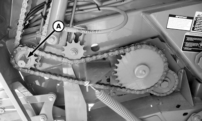
E58888-UN-06AUG10A - Gear Case Hex Shaft
Rotate pickup reel by turning gear case hex shaft (A) using an open-end wrench. -
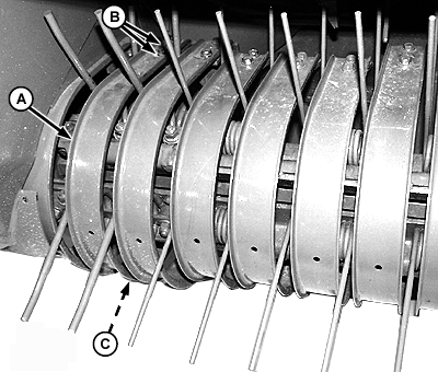
E48047-UN-20JUL00Right-Hand End, 4 ft MegaWide™ Plus Shown
A - Stripper
B - Self-Tapping Cap Screw (2 used)
C - Nut (2 used)
Loosen self-tapping cap screws (B) and nuts (C) (each stripper). -
Remove strippers (A) that are directly over the damaged teeth.
MegaWide™ Plus Pickups Only
-
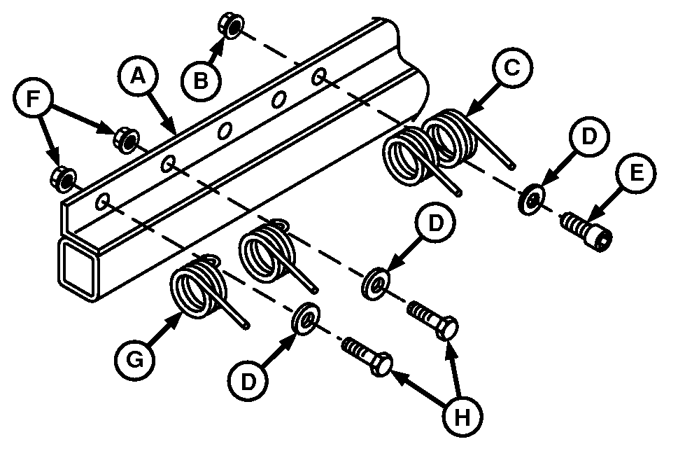
E60331-UN-02AUG11460R MegaWide™ Plus
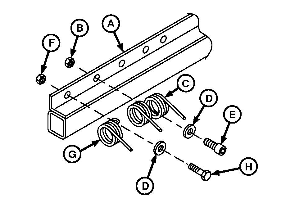
E60332-UN-18JUL11560R MegaWide™ Plus
A - Tooth Bar
B - Lock Nut
C - Tooth or Tines
D - Washer
E - Socket Head Cap Screw
F - Lock Nuts
G - Tooth
H - Cap Screw
Outside teeth (G) are larger than center teeth (C). Outside teeth are single tine pieces and center teeth are double tine pieces. The two types of teeth are mounted to the tooth bar (A) differently. There are large outside teeth on each tooth bar on both left and right-hand ends of pickup.Right-hand end shown. Number of large outside teeth on each end of tooth bar:
- 460R —Two teeth
- 560R —One tooth
Outside teeth: Remove lock nut (F), cap screw (H), washer (D), and tooth or tine (G).
Center teeth: Remove lock nut (B), socket-head cap screw (E), washer (D), and tooth or tines (C).
-
Recommend always replacing hardware when replacing square wire teeth.
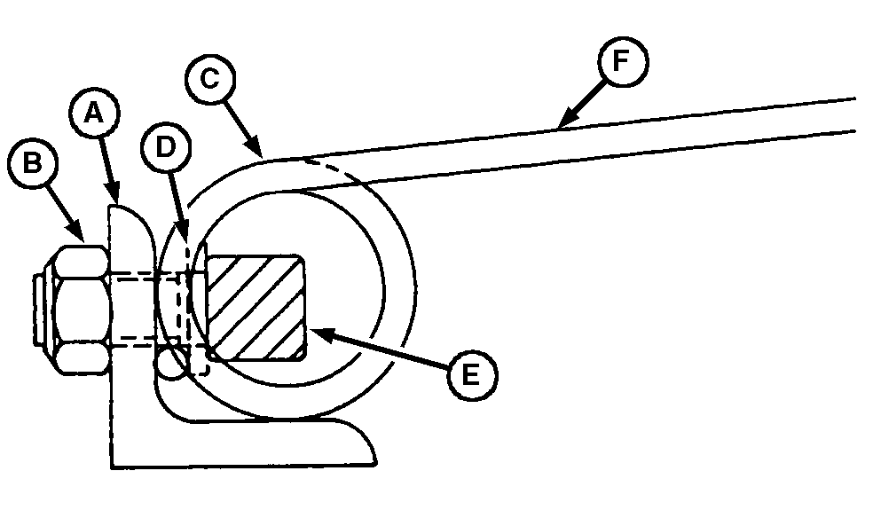
E48049-UN-26MAY00Center Tooth or Tines
A - Tooth Bar
B - Lock Nut
C - Tooth Coil
D - Washer
E - Socket Head Cap Screw
F - Tooth or Tine
Install new teeth in reverse order of removal using the following special instructions:- Coil (C) must rest against the inside angle of bar (A) with tooth or tine (F) pointing away from bar.
- Washer (D) must be installed in position shown to fasten tooth to bar.
-
Tighten lock nuts to specifications.
Center Spring Tooth to Tooth Bar Lock Nut Torque 61 N·m (45 lb·ft) Outside Spring Tooth to Tooth Bar Lock Nut—Two Single Teeth With Strap Torque 61 N·m (45 lb·ft) Outside Spring Tooth to Tooth Bar Lock Nut—Single Tooth Torque 61 N·m (45 lb·ft) -
If the threads on the self-tapping cap screws become stripped, weld M8 nuts to the bottom side of the pickup frame strap.
Install previously removed strippers over replacement teeth using previously removed hardware. Tighten the self-tapping cap screws to specifications.
Stripper to Frame Self-Tapping Cap Screws Torque 33 N·m (24 lb·ft)
|
DP99999,0000D01-19-20171102 |