Set Twine Spacing
Set Mechanical Twine Arm Spacing
The monitor maintains twine spacing for various bale diameters at rated PTO speed.
-
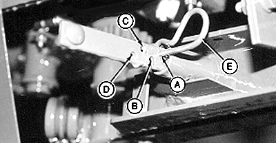
E38438-UN-19JUN96A - 5 cm (2 in) Twine Arm Spacing
B - 10 cm (4 in) Twine Arm Spacing
C - 15 cm (6 in) Twine Arm Spacing
D - 20 cm (8 in) Twine Arm Spacing
E - Spring Pin
Set distance between the twine arms by installing spring pin (E) in the desired position:Hole ID
Twine Arm Spacing
A
5 cm (2.0 in)
B
10 cm (4.0 in)
C
15 cm (6.0 in)
D
20 cm (8.0 in)
-
When operating at rated PTO speed, the twine spacing setting on the monitor must be the same as the mechanical twine arm spacing.
-
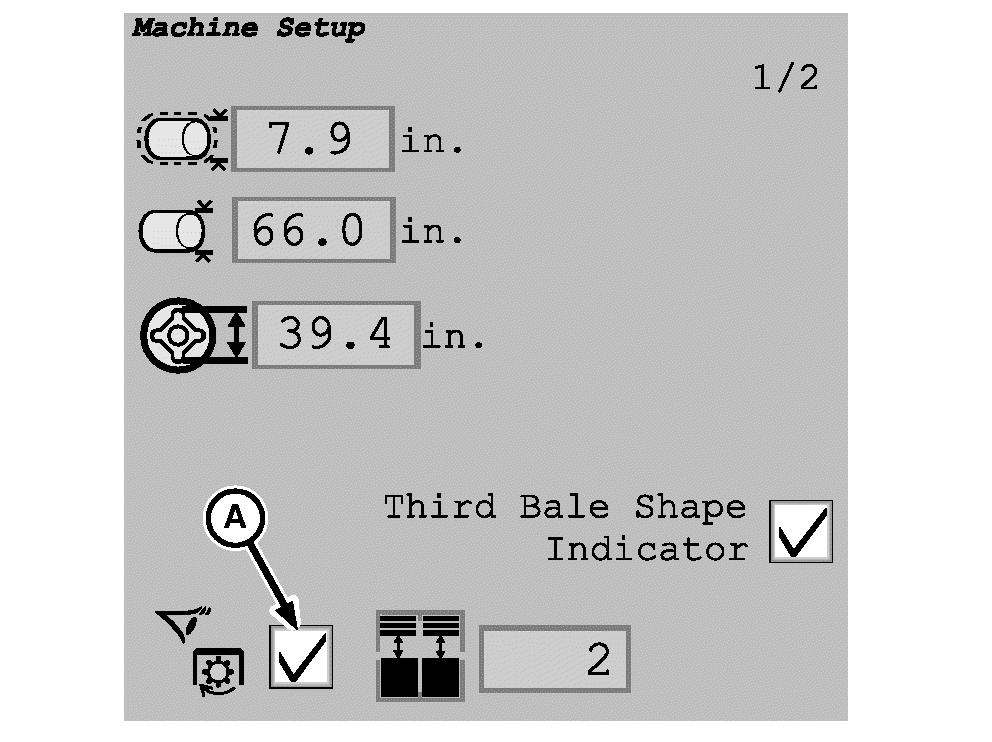
E76600-UN-25JUL14A - Speed Compensation Box
To avoid changes in actual twine spacing on the bale when operating at less than rated PTO speed, turn on the speed compensation program. To turn on the program, check the speed compensation box (A) on the machine setup page. -
If operating at less than rated PTO speed and the speed compensation is not on, set the monitor twine spacing setting less than the mechanical twine arm spacing.
This number can vary with different PTO speeds. Check the twine spacing on the bale and adjust the monitor setting to get the desired twine spacing.
Set Monitor Twine Spacing
-
Turn the tractor ignition key to the ON position. Do not start tractor engine. The monitor receives power through the key-controlled circuit.
-
Select the Baler Main Page softkey.
E84866-UN-05OCT17 -
Select the Wrap Setup softkey on the baler application main page. Ensure that the twine system icon is shown on the wrap setup page
E84878-UN-05OCT17 -
Be sure that the twine spacing setting is the same as the mechanical twine arm spacing setting on the baler.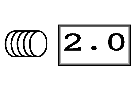
E66971-UN-09AUG12
|
DP99999,0000E4D-19-20171012 |