Adjust Clearance Between Cutter Link Support and Twine Arm
Do not operate twine arms with the pickup in the raised position, or damage to pickup teeth can occur.
-
Turn the tractor ignition key to the ON position.
-
Select the Settings softkey on the baler application main page.
E84879-UN-09OCT17 -
Select the Baler Diagnostics softkey on the machine setup page.
E64643-UN-11MAY12 -
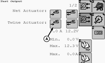
Select the Test Output softkey on the diagnostics page.
E84890-UN-09OCT17 -
E85053-UN-23OCT17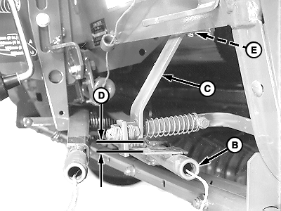
E85166-UN-23OCT17A - Retract Actuator Softkey
B - Twine Arm
C - Cutter Link Support
D - Clearance
E - Shim (as needed)
To move the twine arm (B) under cutter link support (C), select the twine Retract Actuator softkey (A). -
Turn the tractor ignition key to the OFF position and remove key.
-
 Twine arms can move unexpectedly. To avoid crushing,
keep hands out of the twine arm path. Turn off power BEFORE servicing
or adjusting twine arms or twine cutter mechanism.
Twine arms can move unexpectedly. To avoid crushing,
keep hands out of the twine arm path. Turn off power BEFORE servicing
or adjusting twine arms or twine cutter mechanism.Stay out of the path of twine arms at all times when power to twine area is ON.
Measure clearance (D) between the bottom edge of the cutter link support (C) and the top of the twine arm strap. Clearance must be within specifications.
Bottom Edge of Cutter Link Support-to-Top of Twine Arm Strap Clearance 6—12 mm (0.25—0.48 in) (1/4—1/2 in) - If clearance (D) is less than specifications, remove shims (E) between the cutter link support (C) and the crossbeam. If shims do not exist, lower the twine arms relative to the cutter link support. (See Adjust Twine Arm to Starter Roll, Cutter Link Support, and Twine Arm Stop in this section.)
- If clearance (C) is more than specifications, add shims (D).
-
Remove end play at the front of the cutter link support toward the center of the baler. Tighten screws.
|
DP99999,0000E63-19-20171121 |