Adjust Twine Arm to Starter Roll, Cutter Link Support, and Twine Arm Stop
 Twine arms can move unexpectedly when twine arm power
is on. Turn off power to twine arms when standing or placing hands
near twine arms.
Twine arms can move unexpectedly when twine arm power
is on. Turn off power to twine arms when standing or placing hands
near twine arms.
Twine knife has two sharp cutting edges. Be careful when working around the knife.
Adding or removing shims located between the twine arm support and the crossbeam affects dimensions at the following locations:
-
Twine arm to starter roll:
- Twine arm pointing directly toward rear.
- Twine arm toward the right side of baler.
- Twine arm toward the left side of baler.
- Twine arm to cutter link support.
- Twine arm to twine arm stop.
Check dimensions at all locations before performing adjustments. Adding or removing shims at one location can change the dimension at another location.
-
Start the tractor engine and raise the gate fully.
-
Lower the pickup so the twine arms do not contact the pickup teeth.
-
Shut off engine and remove ignition key. Lock the gate.
-
Remove the lower drive roll chain so the starter roll can be rotated by hand.
Adjust Twine Arm to Starter Roll
-
Turn the tractor ignition key to the ON position. Do not start tractor engine.
-
Select the Settings softkey on the baler applications main page.
E84879-UN-09OCT17 -
Select the Baler Diagnostics softkey on the machine setup page.
E64643-UN-11MAY12 -
Select the Test Output softkey on the diagnostics page.
E84890-UN-09OCT17 -
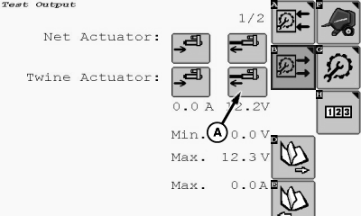
E85052-UN-23OCT17A - Actuator Extend Softkey
Select the twine Actuator Extend softkey (A). -
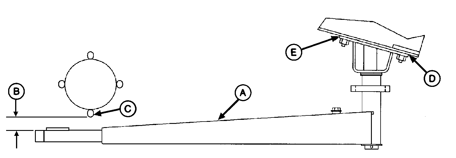
E40616-UN-16DEC97A - Twine Arm
B - Dimension
C - Starter Roll Rod
D - Shim Location
E - Shim Location
Operate the twine arm actuator until the rear twine arm (A) points to the rear of the baler. -
Turn the tractor ignition key to the OFF position and remove key.
-
Rotate the starter roll until the starter roll rod (C) is closest to the twine arm tube.
-
By hand, remove end play at the end of the twine arm toward the starter roll. Check dimension (B) between starter roll rod (C) and the twine arm tube and compare to specifications.
Starter Roll Rod to Twine Arm Tube Distance 6—12 mm (1/4—1/2 in) -
If dimension (B) is less than specified:
-
Remove shims, as necessary, at location (D) between the twine
arm support and the crossbeam. Remove an equal number of shims at
the right-hand and left-hand mounting bolts. (One shim moves the twine
arm approximately 3 mm [1/8 in].)
OR
- Add shims, as necessary, at location (E) between the twine arm support and the crossbeam. Add an equal number of shims at the right-hand and left-hand mounting bolts.
-
Remove shims, as necessary, at location (D) between the twine
arm support and the crossbeam. Remove an equal number of shims at
the right-hand and left-hand mounting bolts. (One shim moves the twine
arm approximately 3 mm [1/8 in].)
-
If dimension (B) is more than specified:
-
Remove shims, as necessary, at location (E) between the twine
arm support and the crossbeam. Remove an equal number of shims at
the right-hand and left-hand mounting bolts. (One shim moves the twine
arm approximately 3 mm [1/8 in].)
OR
- Add shims, as necessary, at location (D) between the twine arm support and the crossbeam. Add an equal number of shims at the right-hand and left-hand mounting bolts.
-
Remove shims, as necessary, at location (E) between the twine
arm support and the crossbeam. Remove an equal number of shims at
the right-hand and left-hand mounting bolts. (One shim moves the twine
arm approximately 3 mm [1/8 in].)
-
Turn the tractor ignition key to the ON position. Do not start the tractor engine.
-
Select the Settings softkey.
E84879-UN-09OCT17 -
Select the Baler Diagnostics softkey.
E64643-UN-11MAY12 -
Select the Test Output softkey.
E84890-UN-09OCT17 -
E85052-UN-23OCT17A - Actuator Extend Softkey
Select the twine Actuator Extend softkey (A). -
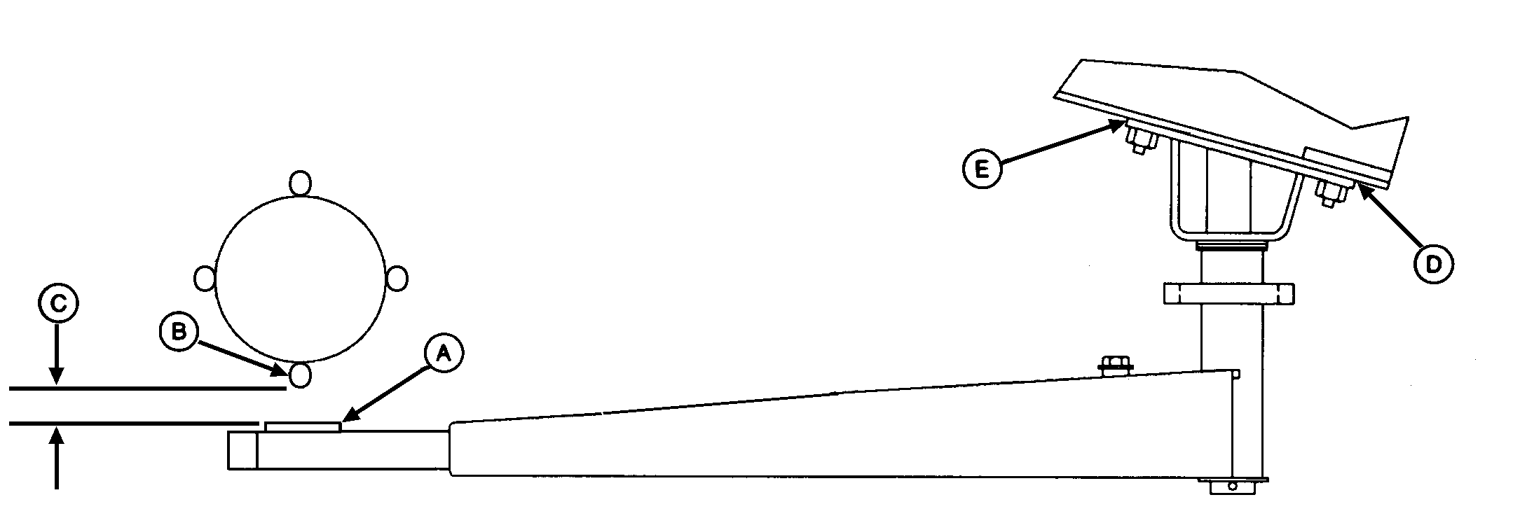
E41680-UN-31OCT96A - Strap
B - Starter Roll Rod
C - Dimension
D - Shim Location
E - Shim Location
Operate the twine arm actuator and move the twine arms to the right-hand side of center so that strap (A) is below the starter roll rod (B). -
Turn the tractor ignition key to the OFF position and remove key.
-
Rotate the starter roll until the starter roll rod (B) is closest to the twine arm strap (A).
-
By hand, remove twine arm end play at the end of the twine arm toward the starter roll.
-
Check dimension (C) between starter roll rod (B) and strap (A) and compare to specifications.
Starter Roll Rod to Strap Clearance (Minimum) 3 mm (1/8 in) -
If dimension (C) is less than specified, add an equal number of shims at right-hand location (D and E), or remove an equal number of shims at left-hand location (D) and (E).
-
Turn the tractor ignition key to the ON position.
-
Select the Settings softkey.
E84879-UN-09OCT17 -
Select the Baler Diagnostics softkey.
E64643-UN-11MAY12 -
Select the Test Output softkey.
E84890-UN-09OCT17 -
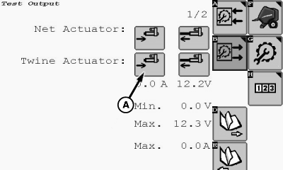
E85053-UN-23OCT17A - Retract Actuator Softkey
Select the twine Retract Actuator softkey (A). -
E41680-UN-31OCT96A - Strap
B - Starter Roll Rod
C - Dimension
D - Shim Location
E - Shim Location
Operate the twine arm actuator and move the twine arm to the left-hand side of center so that strap (A) is below the starter roll rod (B). -
Turn the tractor ignition key to the OFF position and remove key.
-
Rotate the starter roll until the starter roll rod (B) is closest to the twine arm strap (A).
-
Check dimension (C) between starter roll rod (B) and strap (A) and compare to specifications.
Starter Roll Rod to Strap Clearance (Minimum) 3 mm (1/8 in) -
If dimension (C) is less than specified, add an equal number of shims at the left-hand locations (D) and (E), or remove an equal number of shims at the right-hand locations (D) and (E).
Adjust Twine Arm to Cutter Link Support
-
Turn the tractor ignition key to the ON position. Do not start the tractor engine.
-
Select the Settings softkey.
E84879-UN-09OCT17 -
Select the Baler Diagnostics softkey.
E64643-UN-11MAY12 -
Select the Test Output softkey.
E84890-UN-09OCT17 -
E85053-UN-23OCT17A - Retract Actuator Softkey
Select the twine Retract Actuator softkey (A). -
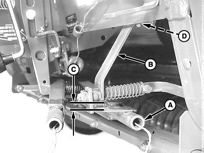
E40634-UN-06SEP00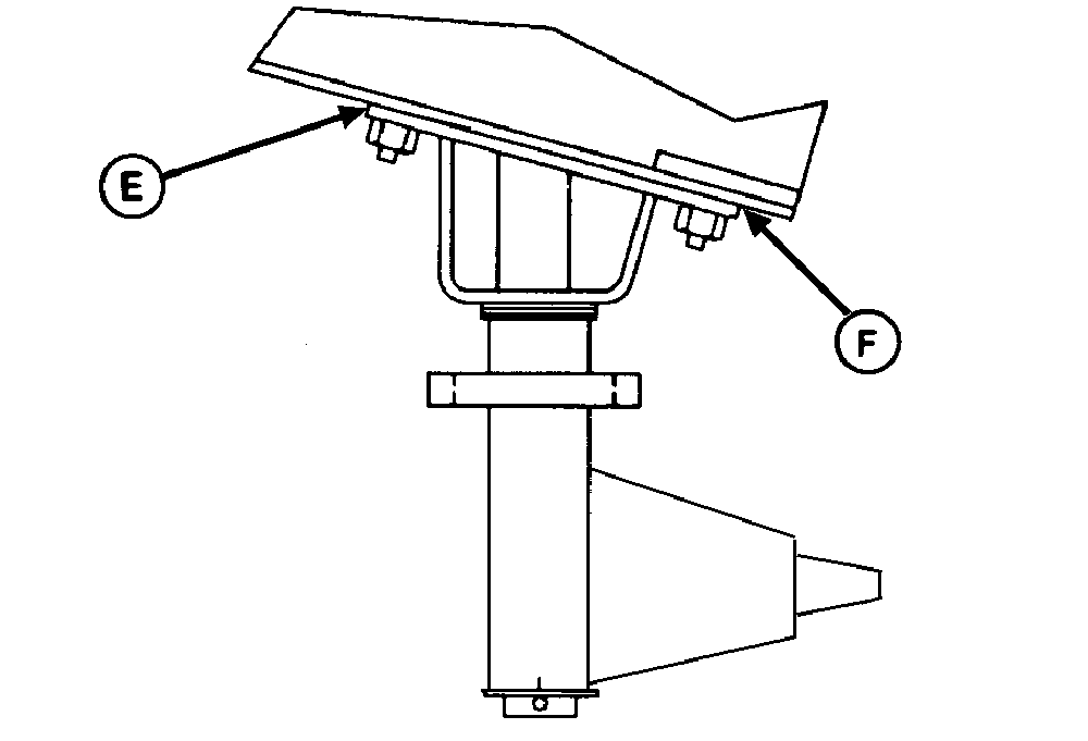
E41682-UN-24OCT96A - Twine Arm
B - Cutter Link Support
C - Dimension
D - Shim Location
E - Shim Location
F - Shim Location
Operate the twine arm actuator and move the twine arms until twine arm (A) lightly contacts the cutter link contact tab. -
Turn the tractor ignition key to the OFF position and remove key.
-
Check dimension (C) between the top of the twine arm strap and the bottom edge of the cutter link support (B) and compare to specifications.
Top of Twine Arm Strap to Bottom Edge of the Cutter Link Support Clearance 6 mm (1/4 in) -
If dimension (C) is less than specified and no shims exist at location (D) between the support (B) and the crossbeam:
-
Add an equal number of shims between the twine arm support and
the crossbeam at left-hand locations (E) and (F).
OR
- Remove an equal number of shims between the twine arm support and the crossbeam at right-hand locations (E) and (F).
-
Add an equal number of shims between the twine arm support and
the crossbeam at left-hand locations (E) and (F).
Adjust Twine Arm to Twine Arm Stop
-
Make sure that the twine arm stop is in the down position.
-
Turn the tractor ignition key to the ON position. Do not start the tractor engine.
-
Select the Settings softkey.
E84879-UN-09OCT17 -
Select the Baler Diagnostics softkey.
E64643-UN-11MAY12 -
Select the Test Output softkey.
E84890-UN-09OCT17 -
E85053-UN-23OCT17A - Retract Actuator Softkey
Select the twine Retract Actuator softkey (A). -
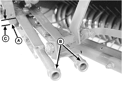
E40623-UN-01JUL96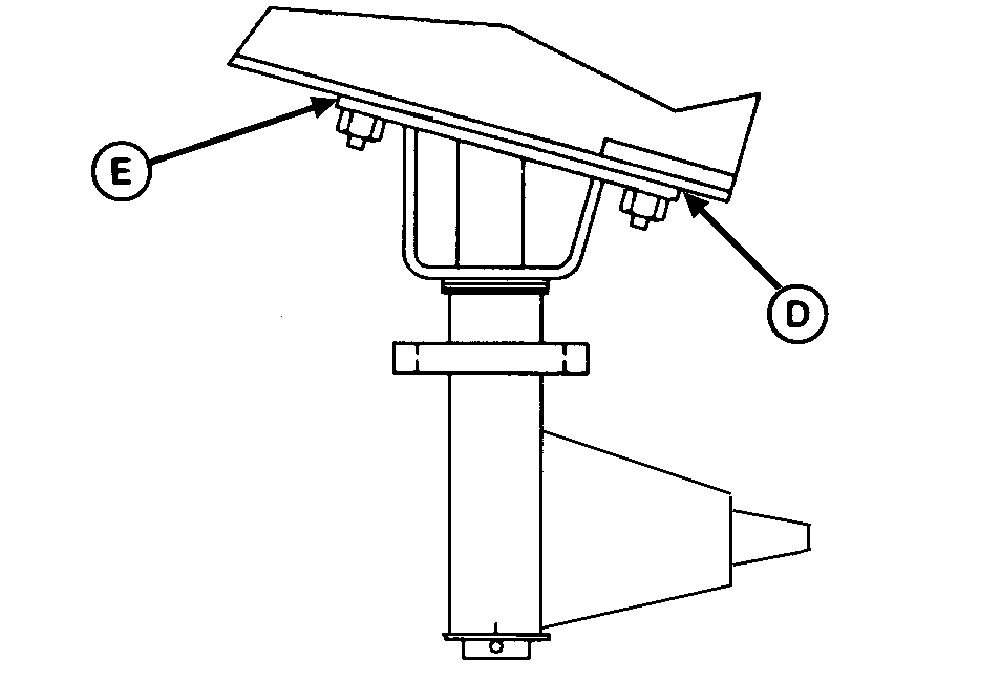
E40617-UN-07OCT96A - Twine Arm Stop
B - Twine Arms
C - Overlap
D - Shim Location
E - Shim Location
Operate the twine arm actuator and move the twine arms (B) to the home position. -
Turn the tractor ignition key to the OFF position and remove key.
-
Check the overlap (C). There must be a minimum overlap between the bottom of stop (A) and the front twine arm according to specifications.
Bottom of Stop to Front Arm Surface Overlap (minimum) 2 mm (3/32 in) -
If overlap dimension (C) is less than specified:
-
Add an equal number of shims at the right-hand locations (D)
and (E).
OR
- Remove an equal number of shims at the left-hand locations (D) and (E).
-
Add an equal number of shims at the right-hand locations (D)
and (E).
Check Twine Arm Adjustments
-
Recheck the following clearances:
-
Twine arm to starter roll
-
Twine arm to cutter link support
-
Twine arm to twine arm stop
-
-
If the twine arm to starter roll dimension has changed due to other adjustments, adjust the number of shims between the twine arm support and the crossbeam as necessary.
-
Adjust twine cutter to twine arm. (See Adjust Twine Cutter to Twine Arm in this section.)
-
Install the lower drive roll chain.
-
Unlock and close the gate.
|
DP99999,0000E68-19-20171121 |