Adjust Net Wrap Counterknife

TS268-UN-23AUG88
-
Turn the tractor ignition key to the ON position. Do not start the tractor engine.
-
Select the Settings softkey.
E84879-UN-09OCT17 -
Select the Baler Diagnostics softkey.
E64643-UN-11MAY12 -
Select the Test Output softkey.
E84890-UN-09OCT17 -
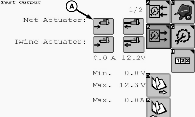
E85171-UN-25OCT17A - Actuator Retract Softkey
To move the surface wrap cut-off arm to the home (downward) position, select the Net Actuator Retract softkey (A). -
Turn the tractor ignition key to the OFF position and remove key. Disconnect the ISOBUS baler plug from the tractor ISO socket or disconnect the plug at the surface wrap connector.
-
Open the net wrap cover.
-
Roll removed for photographic purpose only.
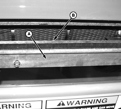
E48362-UN-13JUL00A - Brush
B - Knife
Mark brush mounting positions in order to place the brush back in same position. Remove four nuts, washers, and brush. Set hardware and brush aside for later use. -
To see the alignment between the knife (B) and the counterknife, remove the brush (A).
-
E55777-UN-20MAY08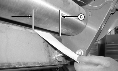
E55778-UN-20MAY08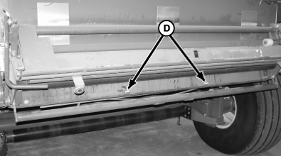
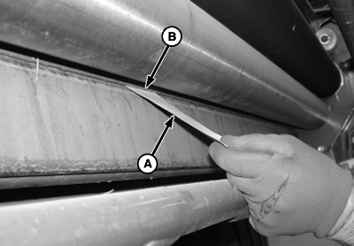
E55788-UN-28MAY08A - Paper, 50 x 100 mm (2 x 4 in)
B - Counterknife Angle
C - Area, 102 mm (4.0 in)
D - Center Knife Bolts (2 used)
With a piece of note pad paper (A), approximately 50 x 100 mm (2 x 4 in), insert the paper between the counterknife angle (B) and the knife bevel in the center area of the knife. The paper must not pass in at least one point between center bolts (D) holding the knife. -
With paper, check a 102 mm (4.0 in) area (C) at both ends of the knife. Paper must not pass in at least one point within the 102 mm (4.0 in) area.
If paper passes through any one of the three areas, see the following checks and adjustments.
-
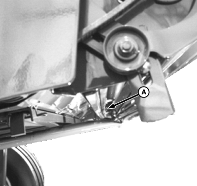
E53027-UN-12JAN04Knife Bowed to Front
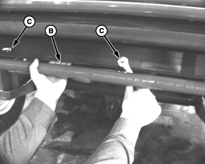
E55755-UN-20MAY08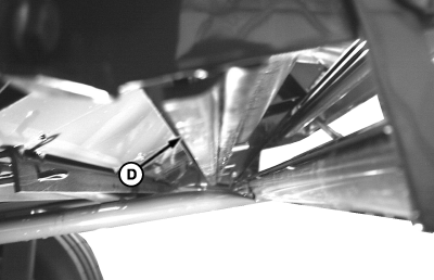
E55779-UN-20MAY08Knife Bowed to Rear
A - Knife Bowed Toward Front of Baler
B - Hand (Pulling Knife Rearward)
C - Center Nuts
D - Knife Shown Bowed Rearward
Clearance between knife and counterknife angle is excessive: Paper passes through center area. Both ends are acceptable. A most likely cause is knife (A) is bowed towards the front of baler.-
Raise the counterknife angle to the highest position using the monitor.
-
Loosen six nuts that hold the knife to the mounting bracket.
-
It is important to maintain straightness of the knife (or a slight rearward bow) to get good net cut-off. Hold the knife in a slightly bowed position while tightening nuts. Once bolts are tight, knife remains straight.
Near the center of the knife, pull the knife and the support rearward by hand (B) until the knife is bowed approximately 2 mm (0.08 in)
-
Bowing the knife rearward more than 4 mm (0.16 in) can cause the center knife angle to catch on the knife edge.
Tighten center nuts (C) while holding the knife in the bowed position. Tighten remaining nuts.
-
Recheck the knife with a straight edge or look down knife from the side of the baler. The knife must be straight (D) or bowed slightly rearward at the center.
-
Recheck the counterknife to knife clearance.
-
-
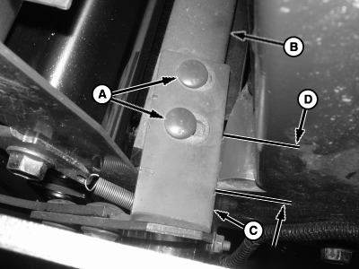
E55727-UN-19MAY08Knife Bolts, Right-Hand Side
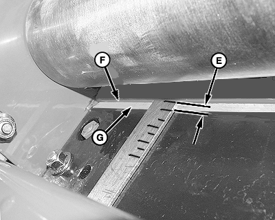
E55776-UN-29MAY08A - Bolts (2 each side)
B - Counterknife Angle
C - Counterknife Support Arm Support
D - Contact Distance
E - Distance, 6—16 mm (0.24—0.63 in)
F - Counterknife Angle Edge
G - Knife Bevel
Right-hand side clearance is excessive: Paper passes through the 100 mm (4.0 in) area.-
With paper, check if the right-hand side of the counterknife angle (B) or the counterknife arm support (C) contacts the baler frame. If contact occurs, raise the counterknife angle and grind the contact area of the frame (D) 1—2 mm (0.04—0.8 in) deep.
-
If paper still passes through on the right-hand side of the knife, adjust bolts (A). Mark the bolt heads relative to the slots as a reference. Raise the counterknife angle to access bolts (A). Measure the distance (E) from the counterknife angle edge (F) to the rear edge of knife bevel (G). Distance (E) must be 6—16 mm (0.23—0.63 in). The distance must be the same on both ends of the knife.
-
Recheck with paper at both ends and the center. If paper passes through on the right-hand side, repeat steps a—c. If paper does not pass in at least one point in the three areas, adjustment is complete.
-
-
Left-hand side clearance is excessive: Paper passes through 100 mm (4.0 in) area
-
Ensure that the right-hand side is not contacting the frame.
-
If the right-hand side contacts the frame, raise the counterknife angle and grind the frame 1—2 mm (0.04—0.08 in) deep. Lower the counterknife angle and recheck both ends and the center with paper.
-
If paper still passes through on the left-hand side, adjust the bolts holding the counterknife angle.
-
Mark the bolt heads relative to the slots as a reference. Raise the counterknife angle to access bolts (A). Measure the distance (E) from the counterknife angle edge (F) to the rear edge of knife bevel (G). Distance (E) must be 6—16 mm (0.23—0.63 in). The distance must be the same on both ends of the knife.
-
Recheck with paper at both ends and the center. If paper passes through on the left-hand side, repeat steps a—e.
-
-
If paper checks are acceptable, install and adjust brush. See Install And Adjust Net Wrap Brush in this section.
-
Connect the net actuator wire connector.
-
Make sure to move the net wrap counterknife fully downward to the home position. If the baler is operated with the counterknife at the up position, net feeds continuously during baling.
Turn the tractor ignition key to the ON position.
-
E84879-UN-09OCT17
Select the Settings softkey.
E64641-UN-11MAY12 -
Select the Baler Diagnostics softkey.
E64643-UN-11MAY12 -
Select the Test Output softkey.
E84890-UN-09OCT17 -
E85171-UN-25OCT17A - Net Actuator Retract Softkey
To move the surface wrap cut-off arm to the home (downward) position, select the Net Actuator Retract softkey (A). -
Turn the tractor ignition key to the OFF position.
-
Close the net wrap cover.
|
DP99999,0000E6C-19-20171121 |