Remove and Install Net Wrap V-Belt
-
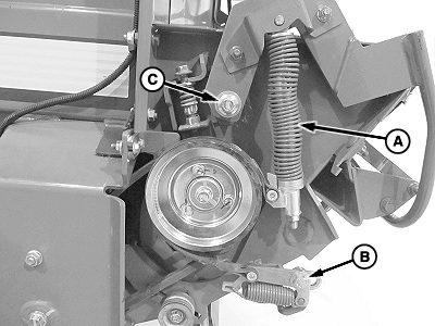
E82244-UN-13FEB17A - Brake Tension Assembly
B - Cap Screw
C - Nut
Start the tractor engine and raise the tension arm fully using the tractor hydraulics. -
Slowly close the gate so the belts remain slack.
-
Shut the tractor engine OFF, set the park brake, and remove the key.
-
Lock the gate and disconnect the ISOBUS power plug from the ISO tractor convenience outlet.
-
Open the net wrap cover.
-
Raise the brake lever and place on the tab.
-
Inspect the bushing and replace if worn.
Remove cap screw (B) and bushing.
-
Remove nut (C), washer, spring, and brake tension assembly (A).
-
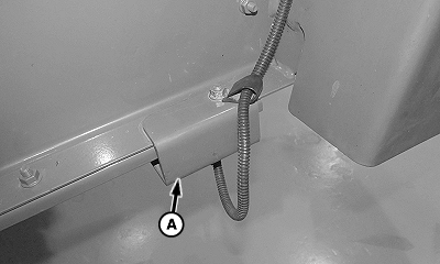
E82247-UN-13FEB17A - B-Wrap Sensor Assembly (if equipped)
Remove the B-wrap sensor assembly (A), if equipped. -
Using a marker, record the net pan settings before loosening the hardware.
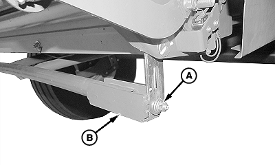
E82245-UN-13FEB17Right-Hand Side
A - Nut
B - Net Pan
Loosen the nut (A) on the right-hand side of the net pan (B). Slide the net pan to the lowest setting in the slotted mounting hole. -
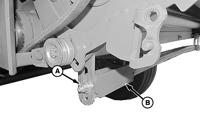
E82246-UN-13FEB17Left-Hand Side
A - Nut
B - Net Pan
Remove the nut (A) on the left-hand side and let the net pan (B) hang. -
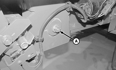
E82248-UN-13FEB17Right-Hand Side
A - Cap Screw
Loosen the roll retaining cap screw (A) on the right-hand side. -
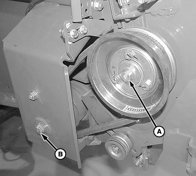
E82249-UN-13FEB17Left-Hand Side
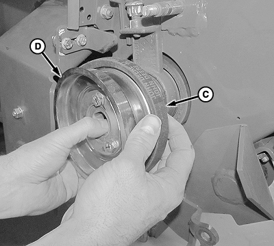
E82250-UN-13FEB17Left-Hand Side
A - Cap Screw
B - Cap Screw
C - V-Belt
D - Brake Sheave
Remove the cap screw (A) from the brake sheave. -
Avoid losing bearing at left end of roll.
Remove the roll retaining cap screw (B) and lower the roll to a suitable jackstand, just below the machine frame.
-
Slide the brake sheave (D) off the end of the shaft.
-
Remove the V-belt (C) from the roller and the brake sheave.
-
Repair or replace parts as necessary.
-
Install in reverse order of removal following this special instruction:
-
Tighten lower rear gate roll cap screws to specification
Lower Rear Gate Roll Cap Screws Torque 140 N·m (105 lb·ft)
-
Tighten lower rear gate roll cap screws to specification
|
DP99999,0000E72-19-20171025 |