Adjust Upper Drive Roll Chain Guides
Belt tension system components and twine guide components have been removed for illustration purposes.
-
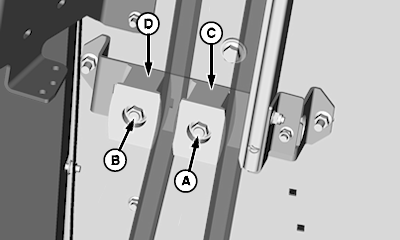
E67750-UN-07SEP12A - Nut, M12
B - Nut, M12
C - Plastic Guide
D - Plastic Guide
Obtain straight upper chain strand by having upper idler spring adjusted, gate closed, belt tensioned, PTO engaged for a few seconds, and PTO and power is shut off. -
Loosen nuts (A and B) and move plastic guide (C) rearward until guide just contacts rear strand of chain. Do not deflect chain. Tighten nut (A).
-
Move plastic guide (C) rearward until front strand of chain deflects and contacts plastic guide (D) and tighten nut (B).
-
Keep flat ends of plastic guides visually parallel to edge of the chain guide bracket while tightening nuts (A and B).
-
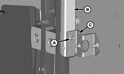
E67748-UN-07SEP12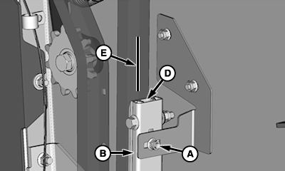
E67749-UN-07SEP12A - Nuts, M8 (1 each bracket)
B - Chain Guide Support
C - Chain Guide Bracket, Lower
D - Chain Guide, Long Plastic
E - Chain Center
To adjust the chain guide support, loosen nuts (A). -
Position chain guide support (B) vertically so lower end contacts short leg of the chain guide bracket (C) and tighten nuts.
-
Position the upper end of the chain guide (D) to be centered within ± 2 mm (0.08 in) of the chain center (E) and tighten nut.
-
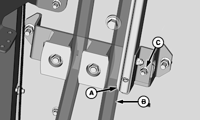
E67747-UN-07SEP12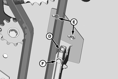
E67751-UN-07SEP12A - Chain Guide, Long Plastic (Lower End)
B - Chain
C - Nut, M8 (1 each bracket)
D - Chain Guide, Long Plastic (Upper End)
E - Nut, M8 (2 used)
F - Cap Screw and Locknut, M10
Move the lower end of the chain guide (A) and chain guide support toward the rear strand of chain (B). Obtain 2 ± 1 mm (0.08 ± 0.04 in) of clearance between the plastic guide and the chain. Tighten nut (C) at the lower bracket. -
Move the upper end of the chain guide (D) and chain guide support toward the rear strand of the chain. Obtain 2 ± 1 mm (0.08 ± 0.04 in) of clearance between the plastic guide and the chain. Tighten nuts (E) at the upper bracket.
-
At the upper end of the chain guide, tighten cap screw and locknut (F) until contact occurs and loosen the locknut approximately 1/2 turn.
|
SF04007,00010B5-19-20171121 |