Check and Adjust Net Wrap Feed Roll Brake
-
 Prevent injury to others. Ensure that bystanders stand
clear before operating the surface wrap unit.
Prevent injury to others. Ensure that bystanders stand
clear before operating the surface wrap unit.The tension spring and the friction of the brake components controls the brake torque. The brake torque is not adjustable. In some dusty conditions, the brake torque can rise, but it does not impact the net wrap system.
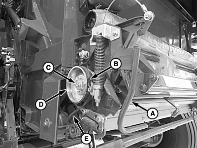
E83522-UN-16JUN17A - Lever
B - Brake Band
C - Cap Screw
D - Sheave
E - V-Belt
Open the net wrap cover. -
Move the brake lever (A) out and up to rest on the latch tab and release the brake band (B).
-
To aid in assembly, record the location and number of shims on both sides of the sheave.
Remove the cap screw (C), washer, shims, sheave (D), and V-belt (E).
-
Connect the baler wiring harness plug to the ISOBUS connector on the tractor.
-
Turn the tractor ignition key to the ON position. Do not start the tractor engine.
-
From the baler application main page, select the Settings softkey.
E84879-UN-09OCT17 -
Select the Baler Diagnostics softkey.
E64643-UN-11MAY12 -
Select the Test Output softkey.
E84890-UN-09OCT17 -
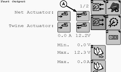
E85461-UN-13NOV17A - Extend Icon
Select the net actuator Extend icon (A) to engage the net wrap actuator and extend the counterknife angle to the highest position. -
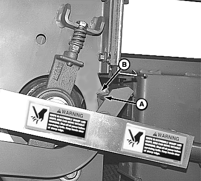
E65146-UN-18MAY12A - Cut-off Arm
B - Tab
Check the position of the right-hand net wrap cut-off arm (A). The arm must contact the tab (B) firmly. If the arm is positioned correctly, proceed to the next step. If the position is not correct, adjust the base end of the mounting bracket as follows to obtain a firm contact:-
Avoid personal injury from an unexpected knife movement.
Disconnect the net wrap actuator connector or power plug when adjusting
or working in the area.
Turn the tractor ignition key to the OFF position.
-
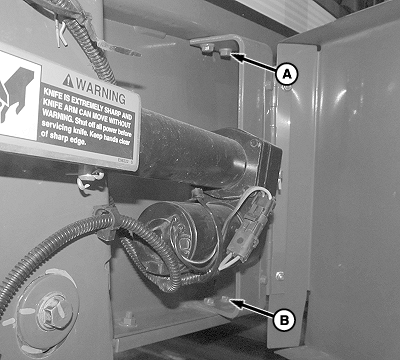
E82308-UN-02MAR17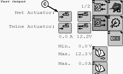
E85462-UN-13NOV17A - Cap Screw (2 used)
B - Carriage Bolt (2 used)
C - Retract Icon
Loosen the cap screws (A) on top of the bracket and the carriage bolts (B) on the bottom end of the bracket. -
Turn the tractor ignition key to the ON position.
-
Select the actuator retract icon (C) and retract the counterknife angle to the shortest position. Tighten the bracket mounting bolts.
-
Extend the actuator and recheck for a firm contact.
-
Retract the actuator fully.
-
Turn the tractor ignition key to OFF and remove the key.
-
-
Install sheave shims as removed. Move shims from inner to outer side of sheave as necessary for proper sheave alignment.
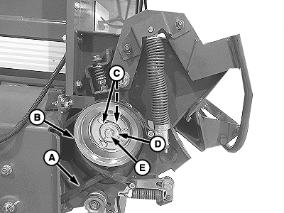
E83523-UN-16JUN17A - V-Belt
B - Sheave
C - Shim
D - Washer
E - Cap Screw
Install the V-belt (A), sheave (B), shims (C), washer (D), and cap screw (E). Tighten cap screw to specification.Cap Screw (E) Torque 40 N·m (30 lb·ft) -
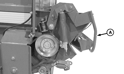
E82258-UN-15FEB17Brake Shown Disengaged
A - Brake Lever
Disengage the net wrap brake lever (A) by placing the lever on top of the lock tab. -
Remove the net wrap from between the rolls.
-
The knife arm must be fully down.
-
Verify that the rubber and steel rolls are clean.
-
Check that the brake band and V-belt sheave are clean and dry.
-
Ensure that the rubber and steel rolls turn freely with the brake lever (A) disengaged.
-
Engage the feed roll brake to the sheave by lowering the brake lever to the bottom of the lock tab.
-
E82303-UN-02MAR17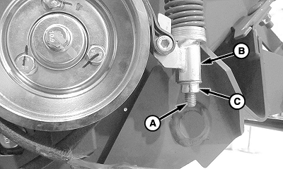
E84164-UN-06NOV17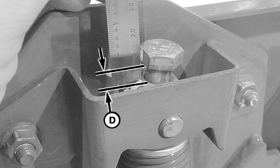
E84165-UN-24AUG17A - Timing Bolt
B - Tension Tube
C - Lock Nut
D - Timing Bolt Gap
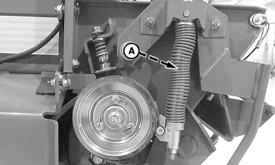
The timing bolt (A) adjusts the spring tension to control brake performance. To ensure that the feed roll brake is applied at the proper time at the end of the wrap application cycle, the timing bolt must be properly adjusted. Incorrect adjustment can result in net material feeding problems.To check for proper brake adjustment, measure the timing bolt gap (D) between the bottom of the timing bolt head and the top surface of the spring plug. The gap must be within specification.
Timing Bolt Gap (D) Distance 1.5—6 mm (0.059—0.236 in) -
Do not adjust the timing bolt before loosening the lock nut, or damage to the brake can result.
The functional range of the timing bolt gap is 1.5—6 mm (0.059—0.236 in).
If the timing bolt gap is not within specification, adjust as follows:
-
Loosen lock nut (C) while holding the tension tube (B) using the wrench flats.
-
Turn the timing bolt (A) while holding the tension tube until the gap (D) is within specification.
-
Tighten the lock nut against the tension tube while holding the tension tube using the wrench flats.
-
-
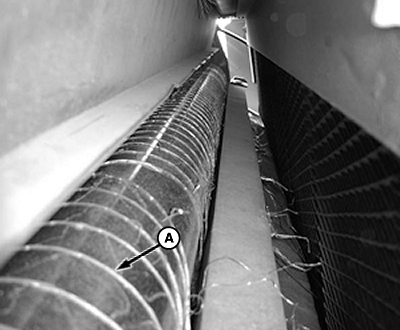
E82721-UN-02MAY17Photo 1—Timing is Correct (Net Wrap Material is Snug Against Steel Roll)
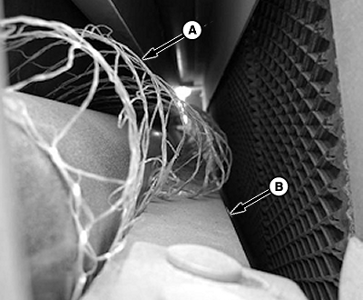
E82722-UN-02MAY17Photo 2—Timing is Late (Net Wrap Material is Looped Above Counterknife)
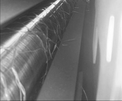
E83751-UN-05JUL17Photo 3—Timing is Early (Broken Net Material Has Snapped Back)
A - Net Wrap Material
B - Counterknife
Verify that the net wrap material (A) is feeding properly:- When the brake timing is correct, the net material (A) is snug against the steel roll as shown in Photo 1.
- If the brake timing is too late, a loop of net can develop above the counterknife (B). The material can get pinched between the front sheet and the rubber roll and cause feeding issues as shown in Photo 2. Adjust the timing bolt to specification.
- If the brake timing is too soon, net snap back can occur and can result in feeding issues as shown in Photo 3. Adjust the timing bolt to specification.
-
After adjustments are made, return the net knife arms to the home position. Turn the ignition key OFF to cancel the STOP alarm. If this procedure is not followed, net feeds continuously during the next bale.
Turn the tractor ignition key to the ON position.
-
To return to the baler application main page, select the Main Page softkey.
E84866-UN-05OCT17 -
Cycle the net wrap actuator by selecting the Start Net Wrapping Cycle softkey. The counterknife must be at the home (downward) position.
E84875-UN-05OCT17 -
Turn the tractor ignition key to the OFF position. Remove the key.
|
SF04007,0001225-19-20180820 |