Adjust Front Twine Arm
-
Turn the tractor ignition key to the ON position. Do not start the tractor engine. Press the ON-OFF key to turn the monitor-controller ON.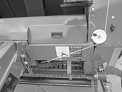
E84161-UN-22AUG17 -
Press and briefly hold the TWINE or NET key to select TWINE mode.
-
Move twine arms to the home position using the monitor-controller RETRACT key.
-
Turn the monitor-controller OFF. Turn the tractor ignition key to the OFF position and remove the key.
-
 Twine arms can move unexpectedly when twine arm power
is on. Turn off power to twine arms when standing or placing hands
near twine arms.
Twine arms can move unexpectedly when twine arm power
is on. Turn off power to twine arms when standing or placing hands
near twine arms.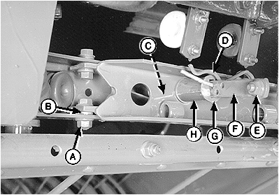
E40629-UN-02JUL96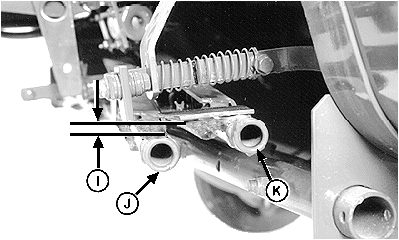
E40628-UN-01JUL96A - Cap Screw and Nut
B - Bushing
C - Spring
D - Spring-Locking Pin
E - Cap Screw and Nut
F - Twine Spacing Strap
G - Washer
H - Spacer
I - Dimension
J - Front Twine Arm
K - Rear Twine Arm
Remove cap screw and nut (E), spring-locking pin (D), washer (G), spacer (H), spring (C), and twine spacing strap (F). -
Measure dimension (I) between the tops of the twine arms (J and K). Twine arm (K) must be higher than twine arm (J) according to specifications.
Top of Front Twine Arm-to-Top of Rear Twine Arm Distance 4.5—7.5 mm (3/16—5/16 in) -
To adjust, loosen nut (A) enough so the end of the twine arm can be moved manually with some resistance.
- If dimension (I) is less than specifications, move end of the twine arm down until correct dimension is obtained.
- If dimension is greater than specifications, move end of the twine arm up until correct dimension is obtained.
-
Tighten nut (A) to specifications.
Twine Arm Pivot Nut Torque 80 N·m (60 lb·ft) -
Check dimension (I). Adjust as necessary.
-
Install the twine spacing strap, spring, spacer, washer, cap screw, and nut. Install spring-locking pin (D) in the desired hole. Adjust the twine spacing. (See SET TWINE SPACING in Operating the Baler section.)
|
DP99999,0000D2A-19-20170822 |