Calibrate Slip Clutch Alert PTO and Drive Roll Speed Sensors
(Channel 206 and 207)
Both the PTO and drive roll speed sensors must be activated within the baler monitor-controller to enable operation of the slip clutch alert feature.
To Calibrate PTO Speed Sensor:
-
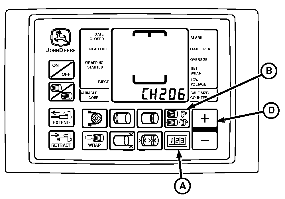
E84589-UN-14SEP17BaleTrak™ Pro Monitor
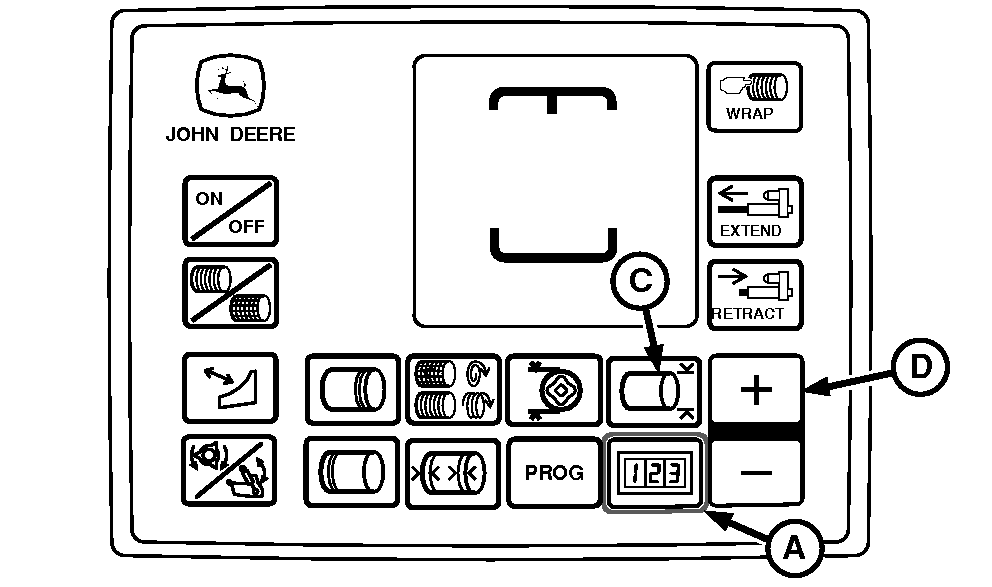
E84266-UN-28AUG17BaleTrak™ Plus Monitor
A - COUNTER Key
B - NUMBER OF WRAPS Key
C - BALE DIAMETER Key
D - PLUS Key
Turn the tractor ignition key to the ON position. Do not start the tractor. -
Access the setup channels as follows:
-
BaleTrak™ Pro Monitor: Press and hold both the COUNTER key (A) and the NUMBER OF WRAPS key (B) while turning the monitor-controller ON.
-
BaleTrak™ Plus Monitor: Press and hold both the COUNTER key (A) and the BALE DIAMETER key (C) while turning the monitor-controller ON.
-
Verify that CH201 is displayed on the monitor.
-
-
Release both keys. The baler model number is displayed. Verify that the model number is correct.
-
Press and hold the COUNTER key and press the PLUS key (D) until CH206 is displayed.
-
Release the COUNTER key.
-
Check the value displayed on the monitor. If necessary, press the PLUS or MINUS key until the value 6 is shown in the display.
-
To enter the setting into memory, turn the monitor-controller OFF.
-
Turn the monitor-controller ON and verify the baler model number. The model number is displayed for approximately 2 seconds. If the model number displayed is not correct, see Baler Model Program (Channel 201) in this section.
-
Turn the tractor ignition key to the OFF position and remove the key.
To Calibrate Drive Roll (Pickup) Speed Sensor:
-
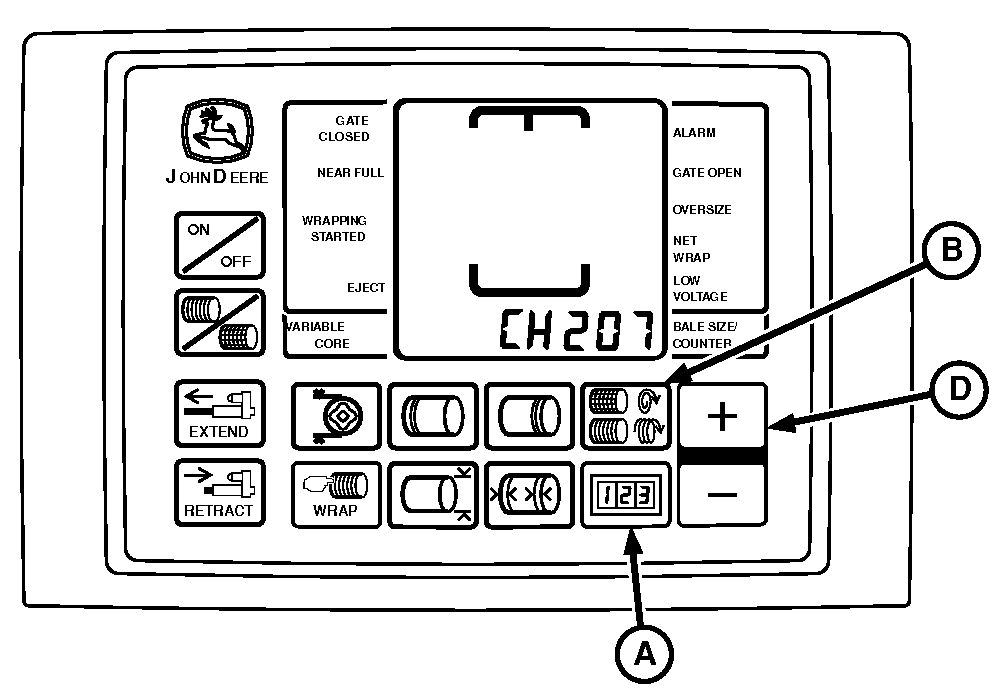
E84590-UN-14SEP17BaleTrak™ Pro Monitor
E84266-UN-28AUG17BaleTrak™ Plus Monitor
A - COUNTER Key
B - NUMBER OF WRAPS Key
C - BALE DIAMETER Key
D - PLUS Key
Turn the tractor ignition key to the ON position. Do not start the tractor. -
Access the setup channels as follows:
-
BaleTrak™ Pro Monitor: Press and hold both the COUNTER key (A) and the NUMBER OF WRAPS key (B) while turning the monitor-controller ON.
-
BaleTrak™ Plus Monitor: Press and hold both the COUNTER key (A) and the BALE DIAMETER key (C) while turning the monitor-controller ON.
-
Verify that CH201 is displayed on the monitor.
-
-
Release both keys. The baler model number is displayed. Verify that the model number is correct.
-
Press and hold the COUNTER key and press the PLUS key (D) until CH207 is displayed.
-
Release the COUNTER key.
-
Check the value displayed on the monitor. If necessary, press the PLUS or MINUS key until the value 6 is shown in the display.
-
To enter the setting into memory, turn the monitor-controller OFF.
-
Turn the monitor-controller ON and verify the baler model number. The model number is displayed for approximately 2 seconds. If the model number displayed is not correct, see Baler Model Program (Channel 201) in this section.
-
Turn the tractor ignition key to the OFF position and remove the key.
Verify Operation and Adjustment of Sensors:
-
Start the tractor engine. Operate the engine at low idle and engage the PTO.
-
Press and hold the COUNTER key while turning the monitor-controller ON.
-
Continue to hold the COUNTER key and press the PLUS key until CH016 appears in the digital display.
-
Release the COUNTER key and the PTO speed is displayed. The speed readout must be stable and not vary by more than 5 rpm.
-
Press and hold the COUNTER key and press the PLUS key until CH017 appears in the digital display.
-
Release the COUNTER key and the pickup drive roll speed is displayed. The speed readout must be stable and not vary by more than 5 rpm.
-
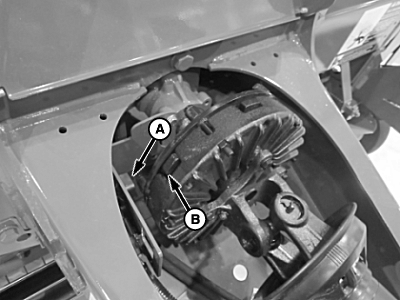
E83755-UN-06JUL17PTO Speed Sensor
E83756-UN-06JUL17Pickup Drive Roller Speed Sensor
A - Speed Sensor
B - Clutch Lobe
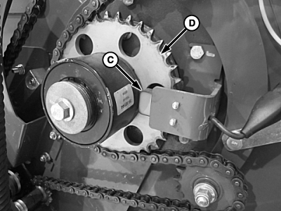
C - Speed Sensor, Pickup Drive Roll
D - Sprocket
If either speed variation exceeds 5 rpm, shut off the tractor engine and remove the key. Adjust speed sensor positions as follows:- Adjust the PTO speed sensor (A) closer to the clutch lobes (B) but not closer than 1 mm (0.04 in).
- Adjust the speed sensor (C) closer to the drive sprocket (D) but not closer than 3 mm (0.12 in). Ensure that the face of the sensor is aligned with the holes in the sprocket.
|
DP99999,0000DAA-19-20171122 |