Adjust PTO and Main Rotor Slip Clutch Alert Sensors (MegaWide™ HC2 Feed System Only)
The following procedure is not used on a 460M or 560M Baler with a regular pickup.
E83416-UN-08JUN17
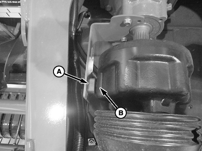
PTO Speed Sensor
E83491-UN-12JUN17
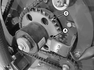
Pickup Main Rotor Speed Sensor
A - Speed Sensor
B - PTO Clutch Fins
C - Tone Wheel
The sensor face must be aligned with the holes in the tone wheel for proper operation. Increasing the gap between the sensor face and the tone wheel can help improve sensor performance.
Clearance between the speed sensor (A) and the PTO clutch fins (B) or the main rotor tone wheel (C) must be within specification. A feeler gauge or washer of the same thickness can be useful in adjusting setting.
| Sensor | Clearance | 3—8 mm (0.12 —0.32 in) |
Verify Operation of Sensors
Verify operation and adjustment of the speed sensors using channel 016 on the monitor-controller for PTO speed and channel 017 for main rotor drive speed.
-
Start the tractor and operate the engine at a low idle. Engage the PTO.
-
Press and hold the COUNTER key while turning the monitor-controller ON.
-
Continue to hold the COUNTER key and press the PLUS key until CH016 appears in the digital display.
-
Release the COUNTER key and the PTO speed is displayed. The speed readout must be stable and not vary by more than 5 rpm.
-
Press and hold the COUNTER key and press the PLUS key until CH017 appears in the digital display.
-
Release the COUNTER key and the main rotor drive speed is displayed. The speed readout must be stable and not vary by more than 5 rpm. The nominal speed is 170 rpm.
Adjusting PTO Sensor
E83494-UN-12JUN17
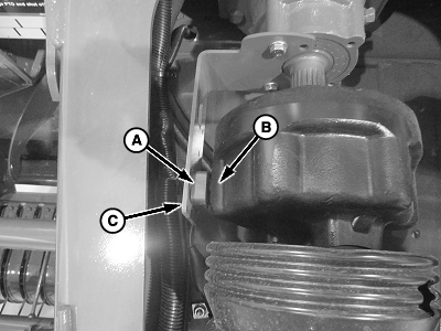
PTO Speed Sensor
A - Sensor
B - Clutch Fins
C - Bracket
Bend bracket (C) as necessary to obtain the specified clearance between the face of the sensor (A) and the clutch fins (B).
| Clearance | 3—8 mm (0.12—0.32 in) |
Adjusting Pickup Main Rotor Sensor
E83495-UN-12JUN17
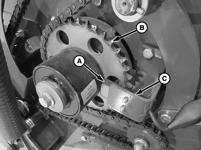
Main Rotor Speed Sensor
A - Sensor
B - Sprocket
C - Bracket
Bend bracket (C) as necessary to obtain the specified clearance between the face of the sensor (A) and the sprocket (B).
| Clearance | 3—8 mm (0.12—0.32 in) |
|
DP99999,0000DB4-19-20171127 |