Check and Adjust Net Wrap V-Belt Idler Tension
-

Protect bystander. To prevent injury, be sure that bystanders stand clear before operating the net wrap unit or baler.
TS268-UN-23AUG88Connect the monitor-controller power plug to the tractor convenience outlet.
-
Turn the tractor ignition key to the ON position. Do not start the tractor engine.
-
Press and hold the COUNTER key while turning the monitor-controller ON. Verify that CH001 appears on the display.
-
Continue to hold the COUNTER key and press the PLUS key until CH018 appears in the display. Release the COUNTER key.
-
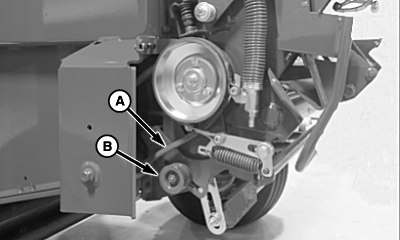
E84231-UN-24AUG17A - V-Belt
B - Idler Pulley
Press the EXTEND or RETRACT key on the monitor until the actuator moves approximately half way up or down and loosens the V-belt (A). -
To avoid personal injury from unexpected knife movement,
disconnect the actuator wire connector or power plug when performing
adjustment or working in the area.
Temporarily move the V-belt from the top of the idler pulley (B) to the underside of the pulley.
-
Reconnect the power source.
-
Press and hold the COUNTER key while turning the monitor-controller ON. Verify that CH001 appears on the display.
-
Continue to hold the COUNTER key and press the PLUS key until CH018 appears in the display. Release the COUNTER key.
-
Press the mode selector switch and place the monitor-controller in the NET mode.
-
Press and hold the EXTEND key until the actuator extends the counterknife angle to the highest position.
-
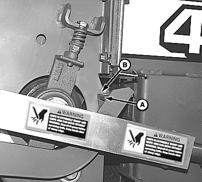
E51045-UN-03JAN02A - Cut-off Arm
B - Tab
Check the position of the right-hand cut-off arm (A). The arm must contact the tab (B) firmly. If the arm is positioned correctly, proceed to the next step.If the position is not correct, adjust the base end of the mounting bracket as follows to obtain a firm contact:
-
Turn off the monitor-controller and disconnect the power plug from the power source.
-
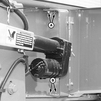
E49027-UN-18OCT00A - Cap Screw (2 used)
B - Carriage Bolt (2 used)
Loosen the two cap screws (A) on the top end of the bracket and the two carriage bolts (B) on the bottom end of the bracket. -
Connect the monitor-controller power plug to the power source. Turn on the monitor-controller and access channel 018.
-
Press the RETRACT key and move the counterknife angle to the shortest position.
-
Tighten the cap screws and carriage bolts on the actuator bracket.
-
Extend the actuator and recheck for a firm contact.
-
-
Press the EXTEND or RETRACT key and return the actuator to approximately half way up or down.
-
Disconnect the actuator from the power source.
-
Move the V-belt to the top of the idler pulley.
-
Reconnect to the power source.
-
Engage the brake before extending the actuator.
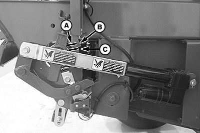
E83253-UN-24MAY17Right-Hand Side
A - Clearance
B - Tab
C - Angle
Extend the actuator. Check that the clearance (A) from angle (C) to tab (B) on the right-hand side sheet is within specifications.Angle-to-Tab On Side sheet Clearance 5—13 mm (0.197—1.512 in) -
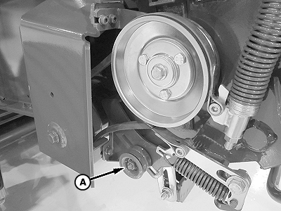
E83406-UN-07JUN17Left-Hand Side Shown
A - Idler Pulley
If the clearance is not within specifications, adjust the idler pulley (A) in the idler arm slot until clearance is within the specified range. -
Retract the actuator and re-extend it to check for correct clearance. If the clearance is still not correct, readjust the idler pulley (A) and recheck.
-
Close the net cover and shut the actuator door.
-
After adjustment, turn the monitor-controller ON. To return the cut-off arm to the home position, press the WRAP key. Turn the monitor-controller off to cancel the STOP alarm. If this procedure is not followed, net will be fed continuously during the next bale.
Connect the monitor-controller power plug to the power source. Turn the tractor ignition key to the ON position. Do not start the tractor engine. Turn the monitor-controller ON.
-
The STOP alarm sounds while cycling the actuator.
Cycle the actuator several times using the WRAP key.
-
Press the WRAP key and return the net knife to the home (downward) position.
-
Turn the monitor-controller OFF.
|
DP99999,0000E04-19-20170914 |