Test Gate Latch Proximity Switches (Channels 014 and 015)
-
Turn the tractor ignition key to the ON position. Start the tractor engine. Using the SCV lever, ensure that the gate is fully closed.
-
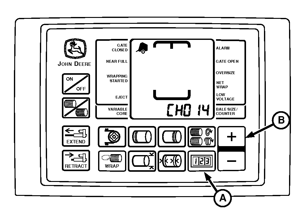
E84666-UN-27SEP17BaleTrak™ Pro Monitor

E84402-UN-31AUG17BaleTrak™ Plus Monitor
A - COUNTER Key
B - PLUS Key
Press and hold the COUNTER key (A) while turning the monitor-controller ON. -
Continue to hold the COUNTER key and press the PLUS key (B) until the digital display shows CH014.
-
Release the keys and view the reading on the display. Verify that the display reads 012.
-
Using the SCV lever, raise the gate to full height.
-
Verify that the display reads 00 and the alarm tone sounds.
-
Using the SCV lever, close the gate. Verify that the display changes back to 12 and the alarm tone goes off.
-
Press the PLUS key until the digital display shows CH015.
-
Release the keys and view the reading on the display. Verify that the display reads 012.
-
Using the SCV lever, raise the gate to full height.
-
Verify that the display reads 00 and the alarm tone sounds.
Diagnostic Channel
Function
Display Reading
Switch Open (Gate Closed)
Display Reading
Switch Closed (Gate Open)
014
Right-Hand Gate Latch Proximity Switch
012
00 (Tone)
015
Left-Hand Gate Latch Proximity Switch
012
00 (Tone)
-
Using the SCV lever, close the gate. Verify that the display changes back to 12 and the alarm tone goes off.
-
If readings are not as shown, adjust switch position and test again. (See ADJUST GATE LATCH PROXIMITY SWITCHES in Service-Baler section.)
-
If switch adjustment does not produce normal readings:
-
Turn the monitor-controller OFF. Turn the tractor key to the OFF position and remove the key.
-
Check the wire harness for cuts and breaks.
-
Check harness connectors for damaged (pushed back) terminals.
-
Check for correct wire connections. (See WIRE HARNESS DIAGRAM—BALER in Service—Baler section.)
-
Replace switch if necessary. (See your John Deere dealer or qualified service provider.)
-
|
DP99999,0000E30-19-20170927 |