Hydraulic System Diagram
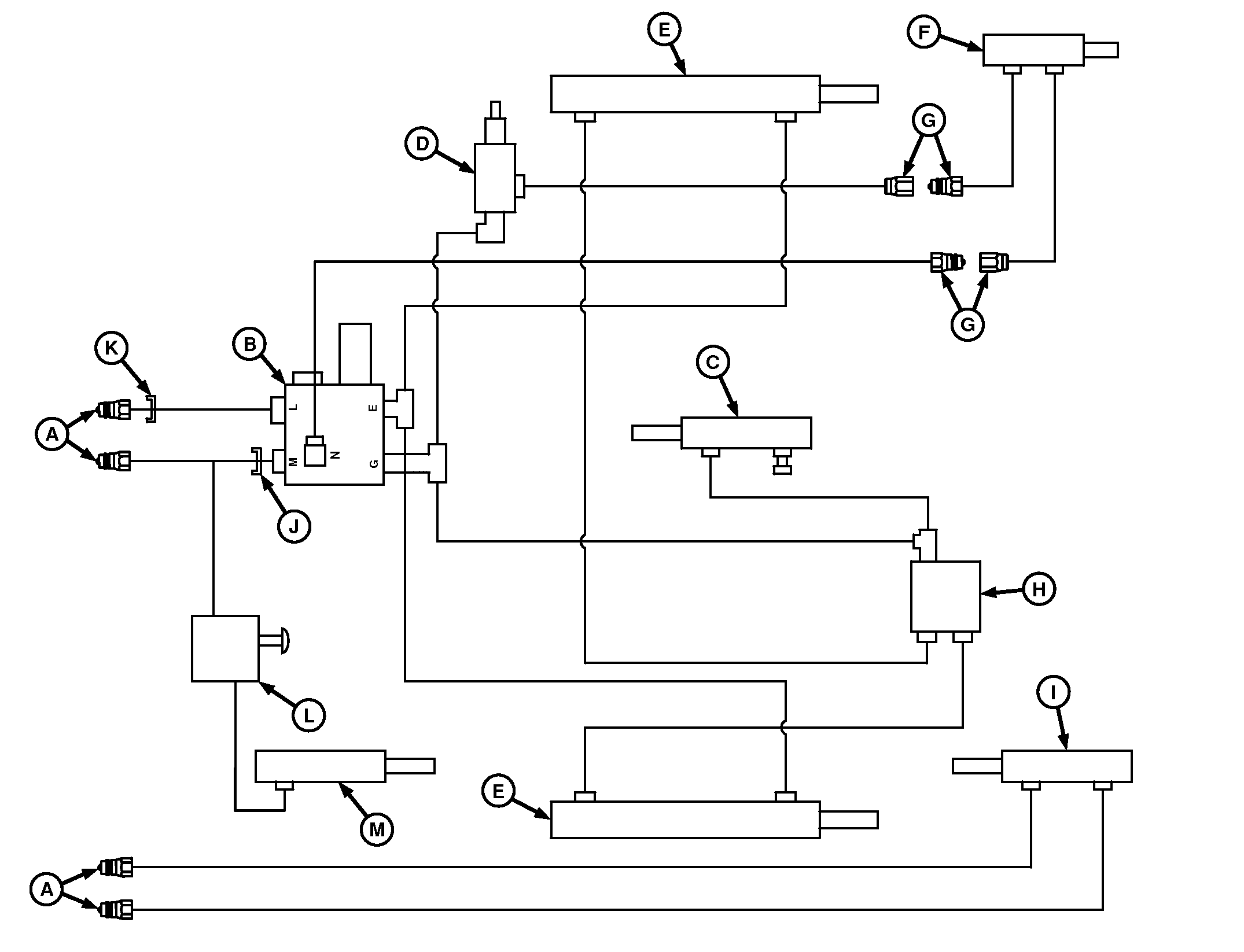
E84046-UN-10AUG17
A - To Tractor SCV Port (2 used)
B - Tensioning Valve
C - Take-Up Arm Cylinder
D - Bale Ramp Regulator Valve (if equipped)
E - Tension or Gate Cylinder (2 used)
F - Bale Ramp Cylinder (optional)
G - Quick-Disconnect Fitting (4 used, if equipped)
H - Gate Lock Valve
I - Pickup Lift Cylinder (if equipped)
J - Orifice (stamped 361)
K - Orifice (stamped 351)
L - Third Roll Drive Valve (precutter only, if equipped)
M - Third Roll Cylinder (precutter only, if equipped)
One set of hydraulic outlets is required to operate the baler.
If the baler is equipped with optional hydraulic pickup lift, an additional set of hydraulic outlets is needed.
An optional hydraulic bale ramp is available. The bale tension or the gate control system operates the bale ramp.
The hydraulic system uses the following major components:
- Tensioning valve (B)—Used to direct oil flow, check flow, and limit hydraulic pressures.
- Tension or gate (double-acting) cylinders (E)—Used to raise and lower gate and to control bale tensioning.
- Take-up (single-acting) cylinder (C)—Used to provide proper sequencing between the tension arm and gate opening. Also, it helps the control belt slack during gate closing to avoid belt pinching.
- Optional pickup lift (double-acting) cylinder (I)—Used to raise and lower pickup using tractor SCV.
- Optional bale ramp (double-acting) cylinder (F)—Used to automatically lower or raise bale ramp when gate is opened fully.
- Optional regulator valve (D)—Used to regulate flow to and from the optional bale ramp cylinder (F) for proper sequencing of ramp and gate positions.
- Gate lock valve (H)—Used to block flow of oil to and from base ports of tension or gate cylinders (E).
- Third roll drive valve (L)—Used to control the flow to the cylinder during the gate open and close cycle. Disengages the third roll drive (extends the cylinder) during opening. Re-engages (springs retract the cylinder) when the gate closes and tension comes down to trigger the poppet valve.
Hydraulic System Diagram—Precutter
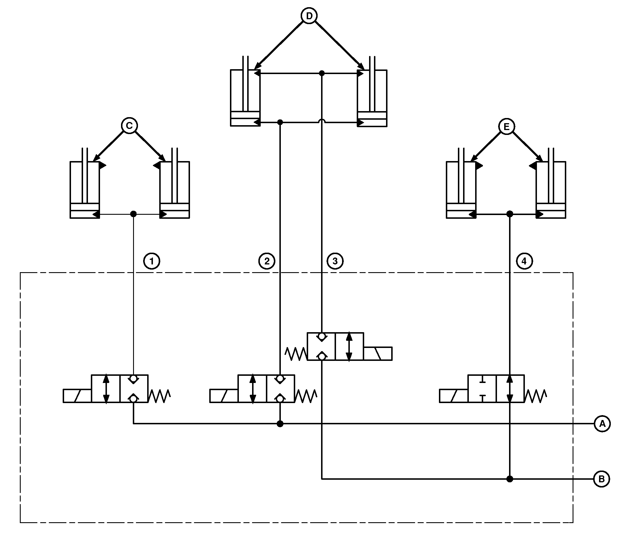
E83624-UN-16AUG17
A - SCV Retract Line
B - SCV Extend Line
C - Knife Engage Cylinder (2 used)
D - Drop Floor Cylinder (2 used)
E - Pickup Lift Cylinder (2 used)
1 - Port D
2 - Port E
3 - Port F
4 - Port G
|
DP99999,0000E31-19-20170927 |