Adjust Gate Latch Stop
-
Door is removed for illustration purposes only.
E40982-UN-04DEC96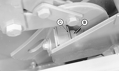
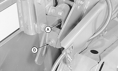
E40983-UN-04DEC96A - Gate Latch
B - Gate Latch Stop
C - Stop Pad
D - Cap Screw
Remove any material buildup between gate and frame. -
Close and latch gate. Push gate latch (A) forward by hand to remove slack. If distance between gate latch stop (B) and stop pad (C) is not within specifications, shim as necessary using the following instructions:
Gate Latch Stop-to-Stop Pad Distance 1—3 mm (1/32—1/8 in.) -
Loosen cap screw (D). (Shims are slotted so cap screw does not have to be removed.)
-
If proper adjustment cannot be obtained, check for twisted gate by closing gate with tractor engine off. If there is a gap on one side when other side is contacting, see your John Deere dealer for correct procedure to straighten gate.
If distance is greater than specified, transfer shims from storage position to shimming position until specification is obtained.
If distance is less than specified, transfer shims from shimming position to storage position until specification is obtained.
-
Center shims and stop pad and tighten cap screw (D). If necessary, repeat procedure on opposite side.
-
-
Check belt tracking. (See CHECK BELT TRACKING in this section.)
|
PP98408,00010D6-19-20130211 |