Adjust Oversize Bale Switch
-
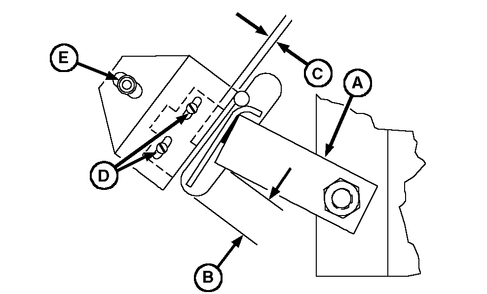
E48030-UN-15MAY00A - Lever
B - Dimension, 13 mm (0.512 in)
C - Clearance
D - Switch Screw (2 used)
E - Cap Screw
Close and latch gate. -
Raise the oversize bale lever (A) to dimension (B) above lower end of slot.
Lever-to-Lower End of Slot Dimension 13 mm (0.512 in) -
Gate must be closed for oversize bale indicator to be displayed.
Check bale lever-to-switch roller contact point. The switch contacts must be closed (indicator or alarm must be activated on the monitor-controller). Clearance (C) between the switch arm and switch body must be within specifications.
Switch Arm-to-Switch Body Clearance 0.79—2.38 mm (0.030—0.100 in) -
If necessary, loosen switch screws (D) and bracket cap screw (E). Position switch so bale lever contacts roller at point shown.
-
Switch or switch bracket must not interfere with bale lever at any point of lever travel or damage to switch can occur.
To check for interference and binding, raise lever to the top of the slot. Adjust switch if necessary.
-
Confirm switch operation by taking test readings using monitor-controller. (See Adjust Gate Latch Proximity Switches And Adjust Oversize Bale Switch in this section.)
|
SF04007,00010C0-19-20171127 |