Adjust Clearance Between Cutter Link Support and Twine Arm

E47598-UN-07JAN00
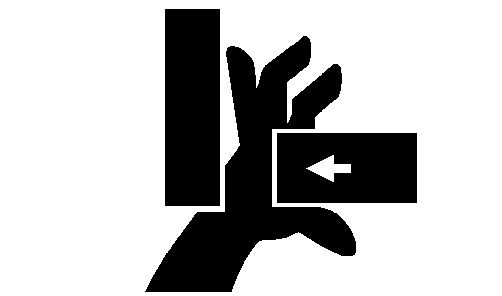
Stay out of the path of twine arms at all times when power to twine arms is ON.
Do not operate twine arms with pickup in raised position, or damage to pickup teeth can occur.
-
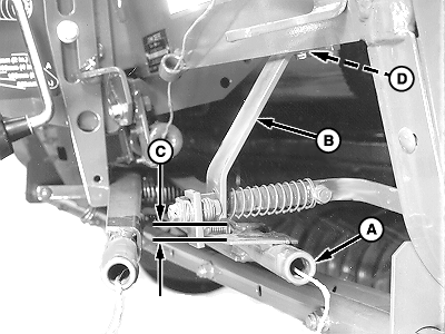
E40634-UN-06SEP00A - Twine Arm
B - Cutter Link Support
C - Clearance
D - Shims
Move twine arm (A) under cutter link support (B) as follows:- Turn tractor key to ON position. Do not start tractor engine.
- Turn monitor-controller ON.
- Press and momentarily hold TWINE or NET key to select TWINE mode.
- Press EXTEND or RETRACT key to move twine arm (A) under cutter link support (B).
- Turn monitor-controller OFF. Turn tractor key to OFF position. Remove key.
Electric Twine Wrap;
-
Measure clearance (C) between bottom edge of cutter link support (B) and top of twine arm strap. Clearance (C) must be within specifications.
Bottom Edge of Cutter Link Support-to-Top of Twine Arm Strap Clearance 6—12 mm (1/4—1/2 in.) - If clearance (C) is less than specifications, remove shims (D) between cutter link support (B) and underneath crossbeam. If shims do not exist, lower twine arms relative to cutter link support. (See ADJUST TWINE ARM-TO-STARTER ROLL, CUTTER LINK SUPPORT AND TWINE ARM STOP in this section.)
- If clearance (C) is more than specifications, add shims (D).
-
Change shims by loosening two self-tapping screws.
-
Remove end play at front of cutter link support toward center of baler. Tighten screws.
|
PP98408,0000F7B-19-20130207 |