Install Gauge Wheels (Regular Pickup)
-
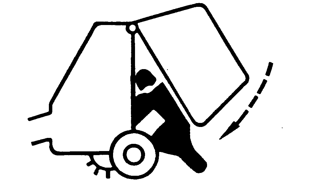
 While working inside or around the baler with an open
gate, the tension arm must be fully raised and against its stops,
and gate lock lever must be moved to locked position (A). Use this
safety feature anytime the gate is open. Close the gate anytime the
baler must be left unattended.
While working inside or around the baler with an open
gate, the tension arm must be fully raised and against its stops,
and gate lock lever must be moved to locked position (A). Use this
safety feature anytime the gate is open. Close the gate anytime the
baler must be left unattended.When positioning the gate to provide access for service, always be sure that tension arm is fully raised, and against its stops. This is to prevent the gate from rotating downward unexpectedly while service work is being performed. ALWAYS raise the gate fully and lower it to the desired opening height before engaging the gate lock. Failure to do this can result in serious injury or death.
Tension arm must remain up against tension arm stops.
TS698-UN-21SEP89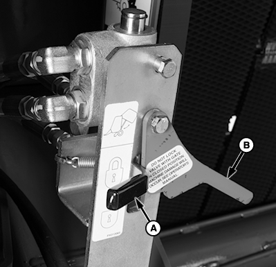
E67269-UN-09AUG12A - Gate Lock Lever
B - Interlock Lever
Start tractor engine, raise gate, and slowly lower gate to slack belts. -
Shut off tractor engine and remove key.
-
Rotate interlock lever (B) and move gate lock lever (A) to locked position (shown).
-
Remove gauge wheels from inside bale chamber. Unlock and lower gate.
-
Open right-hand side door and remove hardware package from twine box.
-
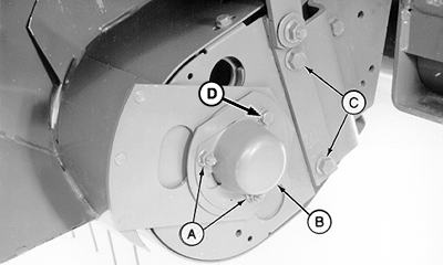
E66614-UN-12JUL12A - Nuts (2 used)
B - Bearing Cover
C - Cap Screws (2 used)
D - Bolt
Remove two nuts (A), bearing cover (B), and two cap screws (C). Discard cap screws. -
Do not remove bolt (D).
-
E40797-UN-23AUG96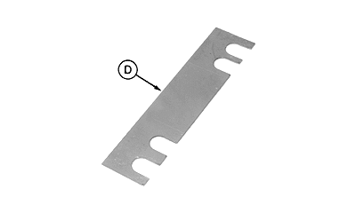
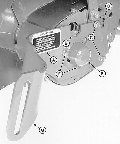
E39329-UN-14MAR96A - Decal
B - Slot
C - Cap Screw, M12 x 60 mm (2 used)
D - Shim
E - Bearing Cover
F - Nuts (2 used)
G - Gauge Wheel Arm
Install gauge wheel arm (G) with slot (B) toward top. -
Install bearing cover (E), nuts (F), cap screws (C). Do not tighten nuts and cap screws at this time.
-
Install shim (D) with notches toward front of baler to avoid binding with flare pivot plate.
Insert shim (D) between arm and frame. Tighten cap screws (C) and nuts (F).
-
Attach decal (A) near top edge of arm as shown.
-
Install wheel. (See INSTALL WHEEL SPINDLES in this section.)
-
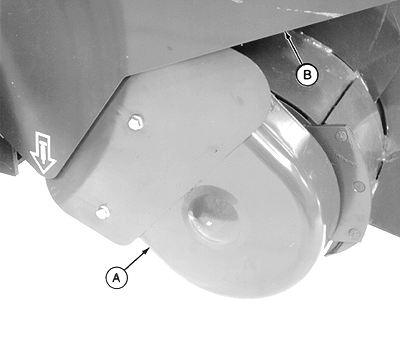
E39320-UN-14MAR96A - Shield
B - Shield
Remove shield (A and B). -
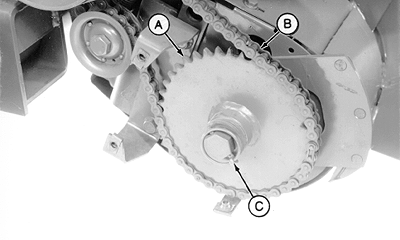
E39321-UN-14MAR96A - Sprocket
B - Chain
C - Quick-Lock Pin
Remove chain (B) from sprocket (A). -
Remove quick-lock pin (C), hex washer, and washers.
-
Remove sprocket (A).
-
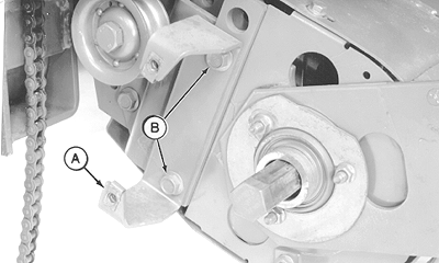
E39322-UN-14MAR96A - Bracket
B - Cap Screws (2 used)
Remove cap screws (B) to remove bracket (A). Discard cap screws. -
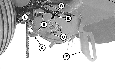
E66615-UN-12JUL12
E39329-UN-14MAR96A - Bracket
B - Cap Screw, M12 x 60 mm (2 used)
C - Nuts (2 used)
D - Shim
E - Slot
F - Gauge Wheel Arm
G - Bolt
Remove nuts (C), then install gauge wheel arm (F) with slot (E) toward top. Install nuts (C), but do not tighten at this time. -
Do not remove bolt (G).
-
Install bracket (A) and cap screws (B). Do not tighten at this time.
-
Install shim (D) between arm (F) and frame. Tighten cap screws and nuts.
-
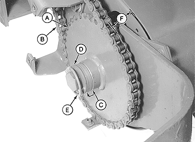
Use 34 mm (1-11/32 in.) [distance (F)] as a starting point to align sprocket (A) to the sprocket with sheave.
Distance (F) is the distance between the outside surface of the end stripper support and inside face of sprocket (A).
E39324-UN-30OCT96A - Sprocket
B - Chain
C - Washer (As Required)
D - Hex Washer
E - Quick-Lock Pin
F - 34 mm (1-11/32 in.) Initial Distance
F - 31 mm (1-7/32 in.) Minimum Distance
Install sprocket (A) with hub toward outside. -
Distance (F) must not be less than 31 mm (1-7/32 in.). If distance (F) is less than specified, sprocket (A) can contact ends of the bearing flange studs or the drive chain can contact the shield bracket.
Check alignment of sprocket (A) to the sprocket with sheave. If sprockets do not align, add or remove washers between sprocket (A) and bearing until alignment is obtained.
If sprocket alignment cannot be obtained while keeping distance (F) at a minimum 31 mm (1-7/32 in.), then the chain idler, sprocket with sheave, and drive sheave must be adjusted accordingly.
-
Install washers (C) (as needed), hex washer (D), and quick-lock pin (E).
-
Install chain (B).
If the chain idler spring was disconnected or removed, install the spring with open portion of top hook toward rear and open portion of bottom hook toward the baler.
-
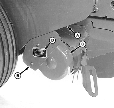
E40799-UN-11OCT12A - Shield
B - Shield
C - Decal
Install shield (A and B). -
Attach decal (C) to shield (A) as shown.
-
Install wheel. (See INSTALL WHEEL SPINDLES in this section.)
|
PP98408,0000FD8-19-20130207 |