Route Twine—Right-Hand Side (Rear Arm)
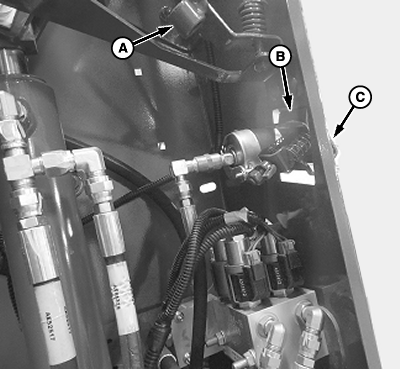
E83245-UN-24MAY17
A - Front Guide
B - Tension Plates
C - Front Side of Baler
-
Detailed threading diagrams are at the right-hand side of the tongue.
Pull twine through the front guide (A) at the front of the twine box.
-
Insert twine between tension plates (B) and pull out through the front side (C).
-
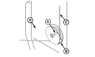
E54349-UN-06JUL05Left-Hand Side Shown
A - Twine Moving Indicator
B - Twine Guide
C - Twine
D - Baler Front Sheet
When using plastic twine and small sisal twine, wrap twine a full turn around twine moving indicator (A). Twine must wrap behind strand which comes down from the twine box. Check that indicator is free to spin. -
Wrapping large sisal twine a full turn around the indicator can cause the twine to cling to itself and break or cause excessive twine tension.
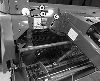
E83244-UN-24MAY17550M Shown
A - Indicator
B - Guide
C - Guide (550M only)
When using large sisal twine, route twine around indicator (A) without making a full turn. -
Route twine through guides (B—C).
-
 Twine arms can move unexpectedly. To avoid crushing,
keep hands out of the twine arm path. Turn off power before servicing
or adjusting twine arms or twine cutter mechanism.
Twine arms can move unexpectedly. To avoid crushing,
keep hands out of the twine arm path. Turn off power before servicing
or adjusting twine arms or twine cutter mechanism.Stay out of the path of twine arms at all times when power to twine arms is ON.
E47598-UN-07JAN00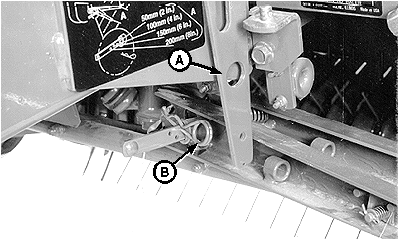
E40126-UN-21JUN96A - Twine Arm Stop
B - Spring Pin
Remove spring pin (B).
-
Lift twine arm stop (A) and move front twine arm away from the rear twine arm.
-
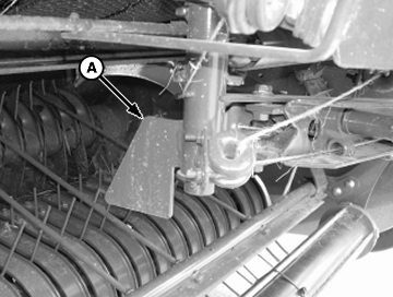
E54717-UN-02JUN08MegaWide™ Pickup Only
A - Baffle Upstop Flag
Ensure that twine is routed over the top of the baffle upstop flag (A). -
Front twine arm is removed for illustration purposes.
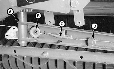
E40127-UN-25JUN96A - Arm Pivot
B - Guide
C - Tab
D - Guide
Route twine behind the arm pivot (A), through guide (B), under tab (C) and through guide (D). -
Remove any crop buildup from tension plates area and make sure twine moving indicator pulleys spin freely.
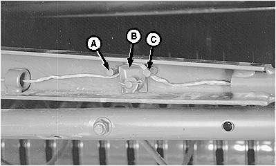
E40128-UN-21JUN96A - Guide Pin
B - Tension Plate
C - Guide Pin
Route twine under guide pin (A), over top of the tension plate (B) and under guide pin (C). Pull on twine to get twine between plates. -
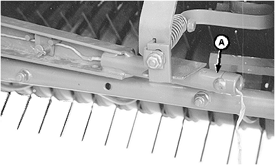
E40129-UN-21JUN96A - Twine Tube
Pull twine through twine tube (A). Pull on twine to remove the slack between the guides. Twine pull must be within specifications with twine perpendicular to the twine arm. To adjust twine tension, see Adjust Twine Tension in Operating the Baler section.Twine Tension Pull (Force) 22—45 N (5—10 lbf) -
Cut twine 305—381 mm (12—15 in) beyond end of twine tube (A).
-
Lift twine arm stop and move front twine arm toward the rear twine arm. Install spring pin, removed in Step 6, in one of the four positions for desired twine spacing.
- BaleTrak™ Pro and Plus System; see Set Twine Spacing in Operating the Baler section.
-
Route twine through the front arm. (See Route Twine—Left-Hand Side [Front Arm] in this section.)
|
BaleTrak is a trademark of Deere & Company |
SF04007,0000E43-19-20170914 |