Adjust Pickup Float Springs—Regular Pickup (450M and 550M)
If equipped with hydraulic pickup lift: Remove cap screw from the base end of cylinder (left-hand side) to gain access for spring adjustment.
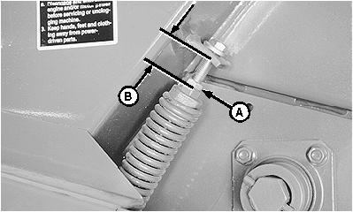
E39271-UN-19JUN96
Right-Hand Side
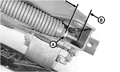
E39270-UN-19JUN96
Left-Hand Side
A - Lock Nut
B - Dimension, Float Spring Setting
Dimension (B) is an initial float spring setting for pickup tooth-to-ground clearance of 25—50 mm (1—2 in) with wheel spindles in the normal position. (See Wheel Spindle Positions in Preparing the Baler section.)More spring force is needed if:
- Operating at pickup tooth-to-ground clearance above 50 mm (2 in) with wheel spindles in the normal position.
- The baler has been lowered at the wheel spindles to improve feeding. (See Bale Short, Dry, Slick Crops in Operating the Baler section.)
Less spring force is needed if:
- The pickup does not lower to desired operating height.
- The pickup bounces too much and leaves crop.
- The baler has been raised at the wheel spindles to improve feeding. (See Bale Cornstalks in Operating the Baler section.)
-
Loosen lock nut (A).
-
Any dimension less than 60 mm (2-3/8 in) at the right-hand spring stretches or weakens the spring.
Tighten screw into spring plug until dimension (B), between the spring plug and the spring anchor is attained.
450M
550M
Without Gauge Wheels
Right-Hand Side
170 mm
(6-11/16 in)
140 mm
(5-1/2 in)
Left-Hand Side
155 mm
(6-3/32 in)
140 mm
(5-1/2 in)
With Gauge Wheels
Right-Hand Side
100 mm
(3-15/16 in)
60 mm
(2-3/8 in)
Left-Hand Side
100 mm
(3-15/16 in)
10 mm
(25/64 in)
-
Tighten lock nut (A).
|
SF04007,0000E68-19-20170913 |