Twine Electric Actuator Installation Adjustment

E47598-UN-07JAN00
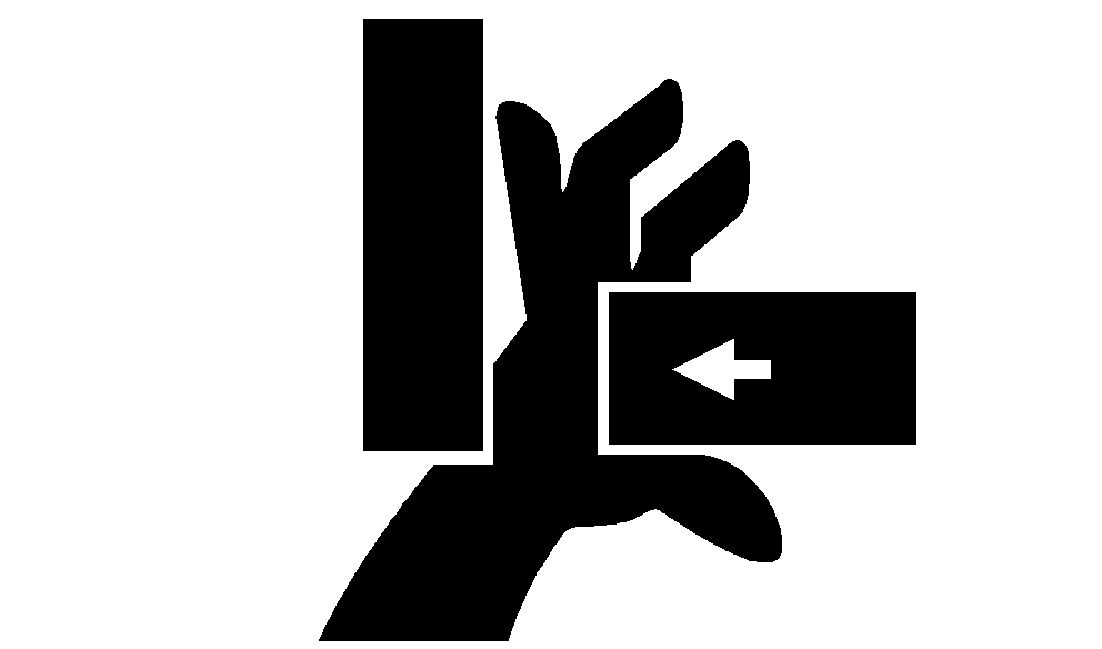
Stay out of the path of twine arms at all times when power to twine arms is on.
450M balers are illustrated for the following procedure. On the 550M, actuator is installed on the right-hand side.
If the electric actuator has been removed or replaced, or the twine cutter tension adjustment cannot be made by moving washers on the cutter strap, make the following adjustment:
-

E40625-UN-06SEP00A - Twine Cutter Strap
B - Contact Tab
C - Twine Arm Stop
Adjust the cutter strap (A) by putting two washers in the front of the contact tab (B) and four washers behind the contact tab (B). Make sure the twine arm stop (C) is in the down position. -
Turn tractor key to ON position. Do not start tractor engine. Set monitor-controller selector switch to TWINE symbol to turn monitor-controller ON.
-
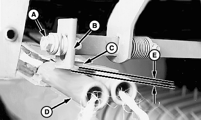
E40583-UN-06SEP00A - Nut
B - Tab
C - Strap
D - Twine Arm
E - Dimension
Press monitor-controller RETRACT key and move twine arms until twine arm (D) lightly contacts the tab (B) and strap (C). -
Set monitor-controller selector switch to OFF (centered) position. Turn tractor key to OFF position. Remove key.
-
Loosen nut (A) and adjust the tab (B) to obtain dimension (E) between the bottom edge of tab (B) and bottom side of strap (C) according to specifications. Keep tab (B) vertical and tighten the nut (A).
Bottom Edge of Tab-to-Bottom Side of Strap Overlap 2—4 mm (3/32—5/32 in) -
Turn tractor key to ON position. Set monitor-controller selector switch to TWINE symbol to turn monitor-controller ON.
-
Move twine arms forward using monitor RETRACT key.
-
Set monitor-controller selector switch to OFF (centered) position. Turn tractor key to OFF position. Remove key.
-
Check overlap dimension (E). Front twine arm must pass under tab (B). If necessary, adjust the tab (B). Light contact between tab (B) and front twine arm (D) is acceptable.
-
Turn tractor key to ON position. Set monitor-controller selector switch to TWINE symbol to turn monitor-controller ON.
-
Move twine arms behind twine cutter using monitor-controller EXTEND key.
-
Set monitor-controller selector switch to OFF (centered) position. Turn tractor key to OFF position. Remove key.
-
Be careful when working around the knife. It is sharp.
TS268-UN-23AUG88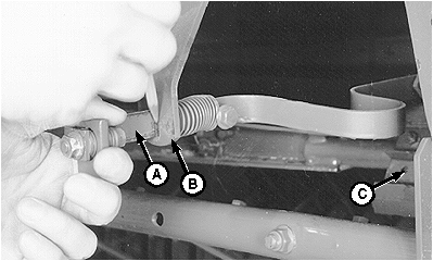
E39276-UN-19JUN96A - Cutter Strap
B - Support
C - Knife
Pull cutter strap (A) gently forward until knife (C) contacts hex anvil. Remove slack, but do not deform the cutter strap. -
Mark along the cutter strap (A) at support (B), as shown.
-
E40647-UN-17JUL96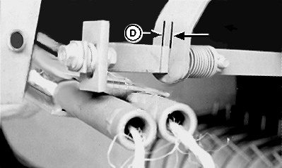
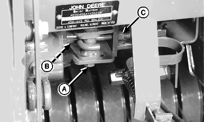
E40626-UN-29JUN96A - Cap Screw
B - Cap Screw
C - J-Bolt Nut
D - Twine Cutter Dimension
Loosen cap screw (A and B). -
Loosen J-bolt nut (C).
-
Move cap screw (A) to end of the slot toward actuator.
-
Tighten cap screws (A and B) enough so actuator pivot can be moved by hand, but with some resistance.
-
Turn tractor key to ON position. Set monitor-controller selector switch to TWINE symbol to turn monitor-controller ON.
-
Using monitor-controller RETRACT key, move twine arms to home position.
-
Set monitor-controller selector switch to OFF (centered) position. Turn tractor key to OFF position. Remove key.
-
Tighten J-bolt nut (C) to obtain dimension (D) between the mark on the cutter strap and strap support according to specifications.
Mark on Cutter Strap-to-Strap Support Distance 5—7 mm (3/16—9/32 in) -
Tighten cap screw (A) to specifications.
Cap Screw (A) Torque 140 N·m (103 lb·ft) -
Tighten cap screw (B) to specifications.
Cap Screw (B) Torque 95 N·m (70 lb·ft) -
Turn tractor key to ON position. Set monitor-controller selector switch to TWINE symbol to turn monitor-controller ON.
-
Using the monitor-controller RETRACT key, cycle twine arm to home position (actuator fully retracted).
-
Set monitor-controller selector switch to OFF (centered) position. Turn tractor key to OFF position. Remove key.
-
Check twine cutter dimension (D).
-
If dimension (D) is less than specified, loosen cap screws (A) and (B). Tighten J-bolt nut (C) until dimension (D) is obtained. Tighten cap screws (A) and (B).
If dimension (D) is more than specified, loosen cap screws (A and B). Loosen J-bolt nut (C) until dimension (D) is obtained. Tighten cap screws (A) and (B).
|
SF04007,0000E76-19-20170913 |