BaleTrak™ Pro and Plus Monitor-Controller Channels
Channel listings and page numbers can be found under Operating the Baler or Service—Baler in the Contents or under section C in the Index.
Monitor will power off after 30 minutes of inactivity.
|
CUSTOMER and SETUP CHANNELS |
||
|---|---|---|
|
Channel Number |
Contents |
Remarks |
|
001 |
Return to Initial Settings |
Display 050, hold PLUS and MINUS keys simultaneously until 099 shows and then release |
|
002 |
Dry Straw Twine Wrap Program |
Select OFF or ON |
|
003 |
Re-extension Twine Application Program |
Select OFF, 8 for 8 inch spacing, 16 for 16 inch spacing, and 24 for 24 inch spacing |
|
004 |
Cinch Wrap Twine Application Program |
Select OFF or ON |
|
005 |
Adjust Bale Diameter Sensor |
Calibration for the bale diameter sensor. Raise tension arm all the way up. Press PLUS and MINUS keys at the same time to save calibration |
|
006 |
Net Wrap Delay |
Delay can be set between 0—8 seconds |
|
007 |
Adjust Right Belt Shape Display |
Use strap for holding bale shape sensor in the tensioned position then press PLUS and MINUS keys together to save the calibration |
|
008 |
Measurement Units |
Set to English (En) or Metric (Si) units |
|
009 |
Adjust Left Belt Shape Display |
Use strap for holding bale shape sensor in the tensioned position then press PLUS and MINUS keys together to save the calibration |
|
010 |
Adjust Near Full Indicator |
Set near full alarm between 0.5—10.0 inches from the selected bale diameter |
|
011 |
Adjust Bale Shape Sensitivity |
Adjust bale shape sensitivity from 1 (least sensitive) to 5 (fastest reaction) |
|
012 |
Test of the Net Switch |
Shows net switch state. 12 indicates that the switch is mechanically open (closed circuit due to the switch wiring) with a tone and 00 indicates the net cutting. |
|
013 |
Test of the Oversize Switch |
Shows oversize switch state. 12 indicates that the switch is mechanically open and 00 is switch depressed with an audible tone |
|
014 |
Test of the Right Gate Latch Switch |
Right-hand gate latch state. 00 indicates that the gate is closed/switch is active. 12 indicates that the gate is open with a tone |
|
015 |
Test of the Left Gate Latch Switch |
Left-hand gate latch state. 00 indicates that the gate is closed/switch is active. 12 indicates that the gate is open with a tone |
|
016 |
PTO rpm Sensor Output |
Shows the measured/calculated PTO speed in rpm (rated is either 540 or 1000 depending on channel 204 setting) |
|
017 |
Pickup rpm Sensor Output |
Shows the measured/calculated pickup speed in rpm (rated is either 310 for non-precutter or 170 for precutter set with channel 205) |
|
018 |
Test Twine or Net Actuator Current |
Allows the operator to use the extend/retract buttons for the net actuator. Displays draw (1—8 moving or 20—30 stalled) |
|
019 |
Check Tractor Voltage |
Provides supply voltage. 9.7 V is the minimum voltage |
|
020 |
Test of Liquid Crystal Display |
Shows all of the segments on the LCD panel |
|
021 |
Maximum Measured Actuator Current |
Measures maximum actuator current read during the binding cycle |
|
022 |
Top Twine Sensor Pulley Test |
Not used |
|
023 |
Bottom Twine Sensor Pulley Test |
Not used |
|
024 |
Test of the Drop Floor Sensor |
Drop floor sensor. 12 indicates that the switch is open/not active (drop floor down) with a tone, 00 indicates that the switch is closed/acitve |
|
025 |
Test of the Knife Engage Sensor |
Knife engage sensor state. 00 indicates that the switch is open/not active (knives disengaged), 12 indicates that the switch is closed/active (knives engaged with a tone) |
|
026 |
Flax Function |
Not used |
|
027 |
Bale Size Slope Tuning |
Adjustment for the slope used in calculating the bale size. Setting is 2776. |
|
028 |
Field Calibration for Bale Size |
In field bale size calibrations, create 2—3 bales of the same size and measure their bale size. Create a bale of same size and leave in the chamber. Adjust channel value to match measured bale size and press the PLUS and MINUS keys at the same time to save the calibration |
|
029 |
Twine Arm Calibration Value |
Must extend the actuator with 2X4 on the right-hand side of the side sheet. Enter value displayed by holding both PLUS and MINUS keys |
|
030 |
Set Actuator Length |
Sets length of the actuator |
|
031 |
Twine End Stop Adjustment |
Not used, for the single twine arm |
|
032 |
Automatic Tying |
Set automatic tying to ON or OFF |
|
033 |
Set Time of the Twine Eject |
Sets amount of delay time between the finishing twine cycle and displaying the gate open |
|
034 |
B-Wrap Cut Position with Metal Strip |
Sets the number of pulses counted after seeing the metal strip until cutting the B-Wrap (BaleTrak™ Pro: minimum is 16, maximum is 160. Default is 126. Must be a smaller value than Channel 035 |
|
Sets the number of pulses counted after seeing the metal strip until cutting the B-Wrap (BaleTrak™ Plus: minimum is 9, maximum is 88. Default is 69. Must be a smaller value than Channel 035 |
||
|
035 |
B-Wrap Orientation Adjustment |
Sets the number of pulses counted before alerting the operator to turn off the PTO (BaleTrak™ Pro: minimum is 58, maximum is 240. Default is 182. Must be a smaller value than Channel 034 |
|
Sets the number of pulses counted before alerting the operator to turn off the PTO (BaleTrak™ Plus: minimum is 31, maximum is 132. Default is 101. Must be a smaller value than Channel 034 |
||
|
036 |
B-Wrap Optical Sensor Polarity |
Polarity of the B-Wrap sensor (must be set to 0) |
|
037 |
B-Wrap Metal Strip Detection Timeout |
Time out number of pulses for detecting the metal strip for the BaleTrak™ Pro: minimum is 126, maximum is 164. Default is 81. |
|
Time out number of pulses for detecting the metal strip for the BaleTrak™ Plus: minimum is 68, maximum is 90. Default is 150. |
||
|
201 |
Baler Model |
Select the baler model being used (440E, 450E, 450, 550, 460, and 560) |
|
202 |
Activate/Deactivate Twine |
Enable twine option. 0 turns off the twine option and 1 turns the twine option on |
|
203 |
Activate/Deactivate Net Wrap |
Enables net option. 0 turns off the net option and 1 turns net option on |
|
204 |
PTO rpm Sensor Setup |
540 selects a 540 rpm PTO speed, 1000 selects a 1000 rpm PTO speed |
|
205 |
Pickup rpm Sensor Setup |
Enables slip clutch detection. 0 turns off feature. For BaleTrak™ Pro, 310 selects 310 rpm for drive roll sensing with Channel 209 forced to 0. For BaleTrak™ Plus, 170 selects 170 rpm for rotor shaft with Channel 209 forced to 1 |
|
206 |
PTO rpm Pulses Per Revolution |
Sets the numbers of pulses the PTO speed sensor sees in a revolution. Set to 6 |
|
207 |
Pickup rpm Pulses Per Revolution |
Sets the numbers of pulses the Pickup speed sensor sees in a revolution. Set to 6 |
|
208 |
Activate/Deactivate Variable Core |
Enables the variable core. 0 turns off the variable core and 1 turns on the variable core. |
|
209 |
Precutter Pickup Type |
Precutter enabled, set to 1 for a precutter machine and 0 for a non-precutter |
|
210 |
Enable Twine Pulley Sensors |
Not used |
|
211 |
Rotational Sensor Type |
Indicates whether the old rotational sensors or the new rotational sensors are used. Set to 1 |
|
Entering 100 Level Channels (Channels 0—37) |
See Display 1 and Display 3 |
Enter 100 level channels by holding the Counter button and then powering on the monitor. To move the channels up or down respectively, navigate to the different 100 level channels by holding the Counter button and pressing the + or - buttons. |
|
Entering 200 Level Channels (Channels 201—211) |
See Display 2 and Display 4 |
Enter 200 level channels by holding the Counter and Number of Wraps buttons for the BaleTrak™ Pro or by holding the Counter and Bale Size buttons for the BaleTrak™ Plus and then powering on the monitor. To move the channels up or down respectively, navigate to the different 200 level channels by holding the Counter button and pressing the + or - buttons. |
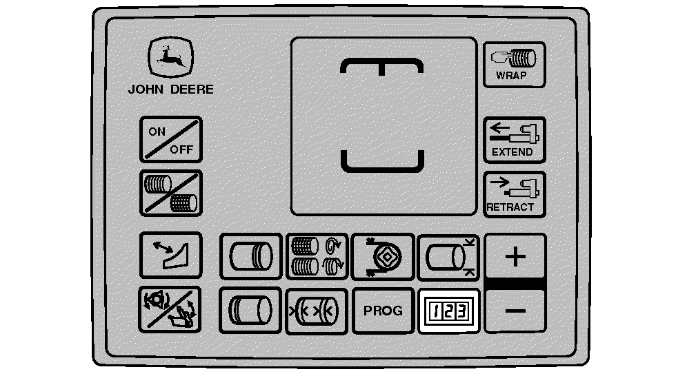
E84321-UN-31AUG17
Display 1—BaleTrak™ Plus
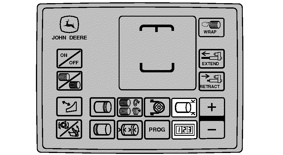
E84322-UN-31AUG17
Display 2—BaleTrak™ Plus
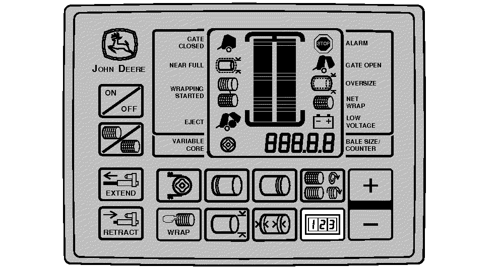
E84323-UN-31AUG17
Display 3—BaleTrak™ Pro
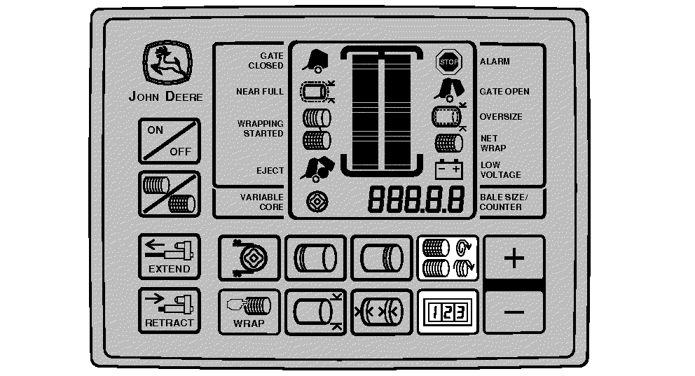
E84324-UN-31AUG17
Display 4—BaleTrak™ Pro
|
BaleTrak is a trademark of Deere & Company |
SF04007,0000F4B-19-20170914 |