Adjust Bale Shape Sensor (Channels 007 and 009)
Number of the bale shape indicator bars displayed is 24.
Bale shape gauge strap (A) is available through your John Deere dealer.
-
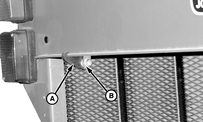
E48271-UN-06JUL00Left-Hand Side Shown
A - Bale Shape Gauge Strap
B - Bearing
If bale shape gauge strap (A) is used:- Install strap (A) over the roller bearing (B).
- Attach end of the strap over the baler frame cross-member. Make sure lip of cross-member is seated on strap.
-
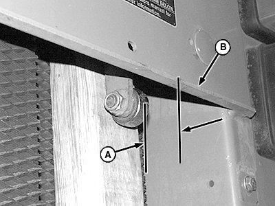
E47620-UN-07JAN00A - Dimension
B - Rear Edge of Panel
If bale shape gauge strap is not used:- Put a board approximately 51 x 102 or 102 x 102 mm (2 x 4 or 4 x 4 in) between the roller bearing and belt as shown.
- Position board to hold bale shape sender arm so the rear of the roller bearing is 62 mm (2-7/16 in) (A) from the rear edge of panel (B).
-
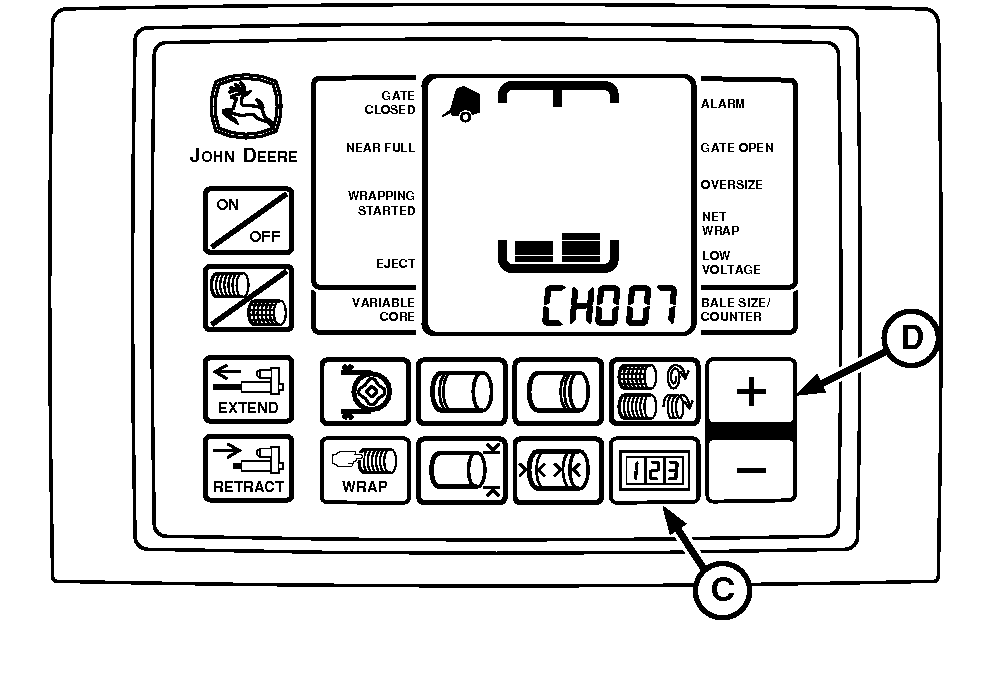
E52527-UN-26JUN03C - COUNTER Key
D - PLUS Key
Press and hold COUNTER key (C) while turning monitor-controller ON. -
Continue to hold COUNTER key (C) and press PLUS key (D) until:
- CH007 is displayed to adjust right side
- CH009 is displayed to adjust left side
-
Release COUNTER key (C) to display sensor value.
-
To calibrate the bale shape sensor, press the plus and minus keys simultaneously. An audible beep is heard.
-
To adjust the opposite side, repeat the procedure. Use appropriate channel for adjustment.
|
SF04007,0000F81-19-20170914 |