Install Left-Hand Upper Drive Roll Bearing
To prevent bearing failure, always loosen the three right-hand side flange mounting bolts (A) before tightening the left-hand side (drive side) center bolt (B). Tighten the left-hand side first, then adjust and tighten the right-hand side mounting bolts.
-
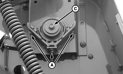
E57624-UN-10JUL09Right-hand Upper Drive Roll Bearing
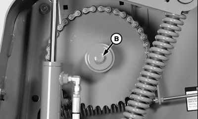
E67576-UN-27AUG12Left-hand Upper Drive Roll Bearing
A - Cap Screw, M8 (2 used)
B - Cap Screw, M10 (drive side)
C - Cap Screw, M12 x 80
Right-hand side of baler: Loosen three flange mounting cap screws (A) and cap screw (C). -
Loosen and remove cap screw (B) on the left-hand side of the baler.
-
Remove drive chain.
-
Carefully remove washers and sprocket, noting the position and number of washers removed at each location.
-
Remove flange nuts.
-
Remove and discard bearing.
-
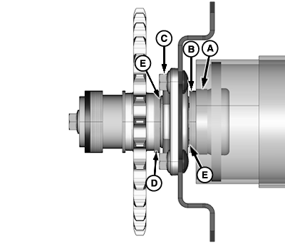
E67561-UN-27AUG12A - Chamfered Spacer
B - Washer (5 used, as required)
C - Flanged Nut
D - Washer (2 used, as required)
E - Washer (2 used) (each side of bearing)
Install chamfered spacer (A) (chamfer toward roll), washers (B), washer (E), and bearing on shaft, snug four flange nuts (C). Pull the roll firmly to left-hand side of the baler. -
Center roll side-to-side:
- Center roll side-to-side.
- Measure from the outer rubber strip to side sheet on both sides to check roll centering.
- The difference between the two dimensions must be 6 mm (0.24 in) or less.
- If needed, add or remove washers between the roll and the left-hand bearing to center roll.
- Washer (E) must be on both sides of bearing.
-
Tighten flange nuts (C) to specifications.
Flange Nut and Bolt Torque 95 N·m (70 lb·ft) -
Install sprocket and two washers (D) and one washer (E). Be sure the washer (E) is next to bearing on both sides.
-
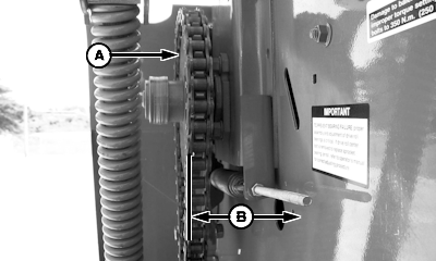
E58846-UN-29JUL10A - Outer Surface of Sprocket
B - Clearance, 89.9 mm (3.54 in)
Measure clearance (B) between the side sheet and outer surface of sprocket (A). Clearance must be within specification.Sidesheet-to-Outer Surface of Sprocket Clearance 89.9 mm (3.54 in) -
If not within specification, add or remove washers between sprocket and bearing as necessary.
-
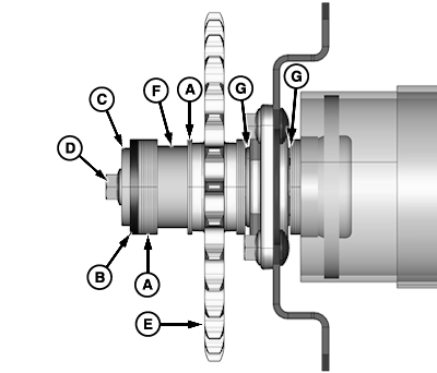
E67562-UN-27AUG12A - Thin Washer (as required)
B - Washer, 6 mm (0.25 in)
C - Washer
D - Cap Screw, M12 x 75
E - Upper Drive Roll Sprocket
F - Spacer
G - Washer (2 used) (each side of bearing)
To remove all the end play to the left-hand side of baler, tap the right-hand side of the upper roll. -
Hold upper roll shaft to the left-hand side and push upper drive roll sprocket (E) and washers inward.
-
To prevent the center bolt loosening or hex knock, keep washers (A and B) centered on shaft. Ensure that the washers do not rotate by hand. Joint must be clamped to eliminate the hex knock.
Install two washers (A) and spacer (F) on shaft.
-
Install washers (A) between spacer and end of shaft, so washers are flush with the end of the shaft, and add one washer (A). Add a washer (B). Install washer (C).
-
Install and tighten cap screw (D) to specification.
Cap Screw Torque 140 N·m (103 lb·ft) -
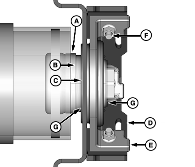
E67519-UN-24AUG12A - Spacer
B - Thin Washer (4 used, as required)
C - Bearing
D - Mounting Strap
E - Cast Housing
F - Cap Screw, M8 (3 used)
G - Washer (2 used) (each side of bearing)
Right-hand Side of Baler: Make sure that there are enough washers (B) between the end of the roll tube and bearing to locate bearing cast housing correctly. Remove three M8 cap screws (F) to be installed later. -
Hold bearing (C) tight against washers. Edge of mounting strap (D) must align within the step of the cast housing (E) in three locations.
-
Washers (G) must be next to bearing on both sides.
-
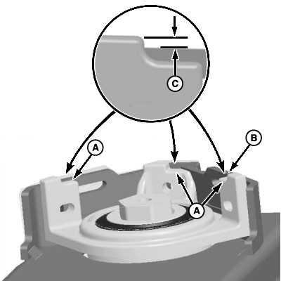
E54509-UN-15MAY06A - Cast Step
B - Mounting Strap Edge
C - Dimension, 1.5—4.5 mm (0.059—0.177 in)
Add or subtract washers behind the bearing, if necessary, to locate cast step (A) correctly with mounting edge (B) in all three locations. Set mounting edge to specification (C).Cast Step Distance 1.5—4.5 mm (0.059—0.177 in) -
Washers (G) must be on each side of bearing.
-
E57567-UN-09JUL09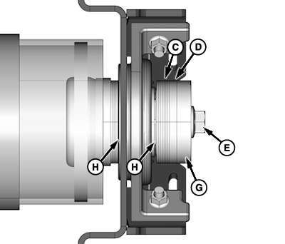
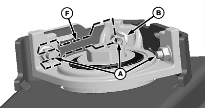
E67520-UN-24AUG12A - Flanged Cap Screw (3 used)
B - Flanged Nut (3 used)
C - Washers
D - Large (Thick Washer)
E - Cap Screw, M12 x 80
F - Shims
G - Washer, 13 x 70 x 12 mm
H - Washer, 45.2 x 57.2 x 0.9 mm
Install three flange mounting cap screws (A) and nuts (B). Only tighten cap screws enough to get a light between the cast flange and mounting strap. Some rotation (a light tap) of the cast flange around the outer race can be required to align flange correctly at all three locations. Do not tighten cap screws at this time. -
Check to see if roll is centered in the hole in the side sheet.
-
To center the roll in the holes in the side sheet, loosen cap screws (A) and flange nuts (B) to insert shims (F) between bearing mounting flange and cast bearing flange.
-
Do not tighten cap screws at this time.
-
Rolls must rotate freely. Check roll clearance through the hole in the side sheet.
If the roll is equipped with wiper pins, it is permissible to grind the drive roll wiper pins to 3 mm (0.12 in) minimum height.
To verify that the clearance with the side sheet hole is according to specifications, spin the upper drive roll. Add or remove shims (F) or move right-hand bearing plate, or grind drive roll wiper pins, if equipped.
Rollers-to-Side Sheet Radial Clearance 1 mm (0.04 in) -
To avoid center cap screw from loosening or hex knock, keep washers (C and D) centered on shaft.
Install one washer (H) and washers (C) between the bearing and the end of the hex shaft. Ensure that the washers are flush with the end of the shaft, then add one more washer. Add large thick ID washer (D). Washer (H) must be next to bearing.
-
Install cap screw (E) and end washer (G).
-
To prevent bearing failure, always tighten cap screw (C) before tightening flange mounting cap screws (A and B).
Ensure that washers do not rotate by hand. Joint must be clamped to eliminate the hex knock.
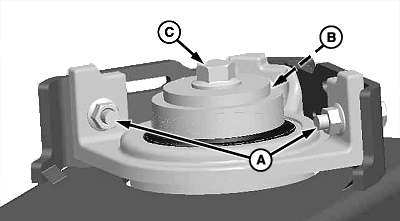
E57566-UN-09JUL09A - Cap Screw, M8 (2 used)
B - Cap Screw, M10
C - Cap Screw, M12 x 80
Tighten cap screw (C) to specification.Cap Screw (M12) Torque 140 N·m (103 lb·ft) -
Tighten middle flange mounting cap screw (B) first. Tighten to specification.
Cap Screw (M10) Torque 80 N·m (59 lb·ft) -
Tighten remaining two flange mounting cap screws (A). Tighten all three cap screws to specification.
Cap Screw (M8) Torque 40 N•m (30 lb·ft) -
To cast the step in three locations, check the position of mounting edge. If mounting edge does not align in the cast sets, repeat steps 19—31.
-
Reinstall and adjust drive chains.
|
SF04007,0000F92-19-20170913 |