Test Drop Floor and Knives Switches (Channel 024 and Channel 025)
-
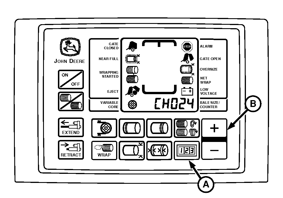
E84260-UN-06SEP17BaleTrak™ Pro Monitor-Controller
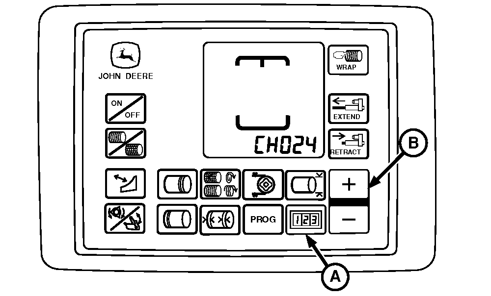
E84261-UN-06SEP17BaleTrak™ Plus Monitor-Controller
Start tractor engine. -
Press and hold the COUNTER key (A) while turning the monitor-controller ON.
-
Continue to hole the COUNTER key and press PLUS key (B) until the digital display shows the desired channel.
-
Release key and view the sensor state as follows:
Diagnostic Channel
Function
Switch Closed
Switch Open
024
Drop Floor Switch
00 (Drop floor up)
12 (Drop floor down with tone)
025
Knife Switch
12 (Knives up with tone)
00 (Knives down)
-
If switch states do not match the readings then perform diagnostics:
- Turn monitor-controller OFF. Turn tractor key to OFF position. Remove key.
- Check for the correct wire connections. (See Wire Harness Diagram —Baler in this section.)
- Check wire harness for cuts or breaks.
- Check harness connectors for damaged (pushed back) terminals.
- Ensure that the sensor face is 3—8 mm (0.118—0.315 in) from the sensing target. Check sensor adjustment.
- Replace switch if necessary. (See your John Deere dealer or qualified service provider.)
|
SF04007,0000FC3-19-20170918 |