Install Driveline (MegaWide Plus and Regular Pickup)
-
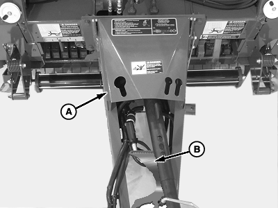
E83254-UN-31MAY17A - PTO Shield
B - Depth Gauge Wheel Arm (2 used)
Remove and discard the shipping wire securing the PTO shield (A). -
Raise the PTO shield.
-
If equipped, remove depth gauge wheel arms (B) from the tongue. Set aside for the depth gauge wheel arm assembly.
Gauge wheel arms are secured to the side of the tongue using shipping wire. Remove and discard.
-
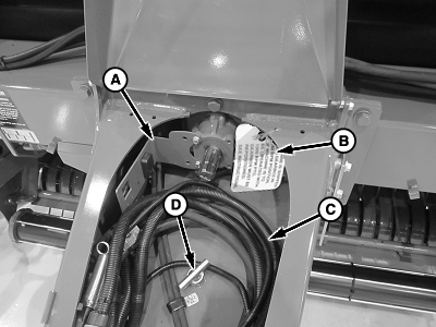
E83413-UN-08JUN17A - Sensor Angle
B - Tag
C - Wire Harness and Hydraulic Hoses
D - Hitch Pin
Remove the hitch pin (D) from the tongue. Set aside for the hitch pin and safety chain assembly. -
Remove and discard the tag (B). Read and understand the tag before discarding.
-
Remove the wire harness and hydraulic hoses (C) from the tongue and set aside.
-
Set aside for the PTO driveline assembly.
-
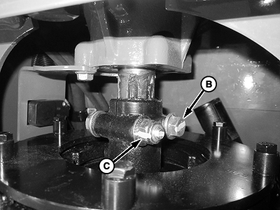
E83415-UN-08JUN17A - PTO Driveline
B - Cap Screw, M12 x 70 (2 used)
C - Lock Nut, M12 (2 used)
If the baler is equipped with a regular pickup proceed to step 19.If the baler is equipped with the MegaWide™ Plus pickup proceed to step 9.
-
Cap screw heads (B) lead as the driveline rotates counterclockwise when looking toward the rear of the baler.
Install the PTO driveline (A) using cap screws (B) and lock nuts (C) (included with the driveline).
Tighten cap screws to specification.
Cap Screw Torque 140 N·m (105 lb·ft) -
Ensure that the wire harness to the sensor is clear of the slip clutch. Damage to the wire harness can occur. Retain the harness to hoses using tie bands.
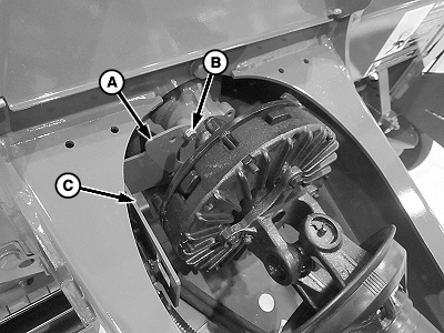
E84060-UN-14AUG17540 rpm Driveline
A - Sensor Angle
B - Cap Screw, M8 x 20 and Flange Nut, M8 (2 each used)
C - Sensor
Install the sensor angle (A) using carriage bolts and flange nuts (B). Leave the hardware loose, the sensor requires adjustment. -
Ensure the sensor (C) is mounted on the side of the bracket facing the PTO slip clutch. Ensure that the sensor is between 3—8 mm (0.118—0.315 in) from the bushing or lobe on the PTO clutch.
-
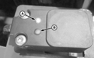
E84255-UN-28AUG17A - Green LED
B - Yellow LED
Verify that the sensor is not damaged.- The green LED (A) lights confirming 5 V power is being supplied.
-
The yellow LED (B) indicates that metal is being detected.
Passing a piece of metal in the front of the sensor while
observing the LED (B) confirms that the switch is working.
-
Recheck 3—8 mm (0.118 ± 0.315 in) clearance between the clutch lobe or bushing and the sensor. Gently pry the PTO clutch forward to simulate PTO driveline thrust loads.
Hold the PTO clutch forward and perform the following:
- If 3—8 mm (0.118—0.315 in) gauge does not pass between the clutch lobe or bushing and the sensor, repeat to obtain the proper clearance.
-
Tighten the tie band around the wiring harness connector and secure to the bracket.
-
Not used on 450M or 550M with a Regular pickup.
PTO and pickup sensor values are set at the factory.
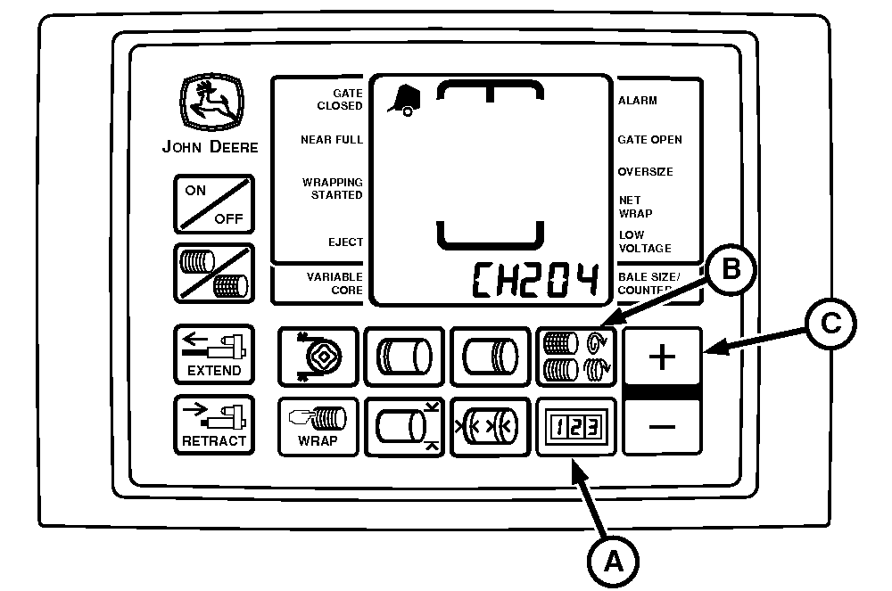
E55069-UN-25APR07BaleTrak™ Pro Monitor-Controller Shown
A - COUNTER Key
B - NUMBER OF WRAPS Key
C - PLUS Key
Verify that the PTO and pickup sensor values are activated using the following procedure:- Turn tractor key to ON position. Do not start the tractor.
- Press and hold both COUNTER key (A) and NUMBER OF WRAPS key (B) for the BaleTrak™ Pro and COUNTER key and the BALE SIZE key for the BaleTrak™ Plus while turning the monitor-controller ON. CH201 must be displayed.
- Release both keys. Baler model is displayed.
- Press and hold COUNTER key (A) and press the PLUS key (C) until CH204 is shown in the display.
- Release COUNTER key (A).
- To change the display to 540 or 1000 PTO speed (depending on machine configuration), press the PLUS key (C).
- Press and hold COUNTER key (A) and press the PLUS key (C) until CH205 is shown in the display.
- To change the display to 310 for non-precutter or 170 for precutter, press the PLUS key (C).
- Press and hold COUNTER key (A) and press the PLUS key (C) until CH206 is shown in the display.
- To change the display to 6 (number of lobes or bushings being detected in one revolution of the PTO), press the PLUS or MINUS key.
- Press and hold COUNTER key (A) and press the PLUS key (C) until CH207 is shown in the display.
- To change the display to 6 (number of holes in the sprocket), press the PLUS or MINUS key.
- Turn monitor-controller OFF.
- Turn tractor key to OFF position. Remove the key.
-
The model number displayed on the monitor-controller must match the baler model number. The twine or net application, slip clutch alert, and optional variable core features only operate correctly if the numbers match.
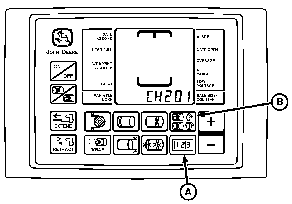
E52456-UN-10JUN08A - COUNTER Key
B - NUMBER OF WRAPS Key
Verify the correct baler model program using the following procedure:- Turn tractor key to ON position. Do not start the tractor.
- Press and hold COUNTER key (A) and NUMBER OF WRAPS key (B) for the BaleTrak™ Pro and COUNTER key and the BALE SIZE key for the BaleTrak™ Plus while turning the monitor-controller ON. CH201 must be displayed.
- Release both keys. Baler model is displayed.
- To change to the desired model, press the PLUS or MINUS key.
- Turn monitor-controller OFF to enter setting into memory.
- Turn monitor-controller ON to verify baler model number. Baler model is displayed for approximately 2 seconds. If displayed baler model number is incorrect, repeat procedure.
- Turn tractor key to OFF position and remove the key.
-
To check the sensor output and verify proper operation, use the following procedure:
- Start tractor, operate at low, but stable, rpm and engage PTO.
- Press and hold COUNTER key while turning monitor-controller ON.
- Continue to hold COUNTER key and press PLUS key until CH016 appears in the digital display.
- Release COUNTER key and PTO speed are displayed. This speed readout must be stable and not vary by more than 5 rpm.
- Press and hold COUNTER key and press the PLUS key until CH017 appears in the digital display.
- Release COUNTER key and pickup drive speed are displayed. This speed must be stable and not vary by more than 5 rpm.
- If there is a variation in either sensor output, shut off tractor and remove the key. Adjust the appropriate sensor closer to the clutch fins or tone wheel, but not closer than 3 mm (0.118 in). Then recheck.
-
With tractor PTO speed of 540 rpm or 1000 rpm (depending on
machine configuration), pickup sensor must read approximately 310
rpm for non-precutter and 170 for precutter. If pickup sensor rpm
is greater than PTO clutch rpm, then orange and brown wires are reversed
at the harness connector.
Example of a problem: Monitor displays slipping. (See Slip Clutch Alert in Troubleshooting section).
If there is a variation in this output, readjust sensors closer to the tone wheel or clutch fins.
Not used on 450M and 550M with a Regular pickup.
Turning PTO Speed Sensor ON and OFF:
- PTO speed sensor can be turned OFF or ON by accessing channel 204.
- Feature can be turned ON by changing the value to 540 rpm or 1000 rpm (depending on the machine configuration).
- Entire slip clutch alert feature can be turned OFF by changing value to 0.
Not used on 450M and 550M with a Regular pickup.
Turning Pickup Speed Sensor ON and OFF:
- Pickup rpm sensor can be turned OFF and ON by accessing channel 205.
- Feature can be turned ON by changing the value to 310 rpm for non-precutter or 170 rpm for precutter.
- Pickup rpm sensor can be turned OFF by changing the value to 0.
- Turning OFF the pickup sensor on channel 205 and turning ON PTO sensor on channel 204 still allows automatic speed compensation during the twine or net application cycle.
|
MegaWide is a trademark of Deere & Company BaleTrak is a trademark of Deere & Company |
SF04007,0001218-19-20180815 |