Adjusting Tractor Drawbar
-
 To avoid personal injury, use locking pins to hold
drawbar stationary when operating PTO-driven implements.
To avoid personal injury, use locking pins to hold
drawbar stationary when operating PTO-driven implements.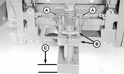
E55187-UN-04JUN07John Deere 7000 Series Tractor Shown
A - Locking Pins
B - Clevis Assembly
C - Drawbar Thickness
Remove locking pins (A) and slide drawbar to center position (shown). -
Install locking pins.
-
Remove clevis assembly (B), if equipped.
-
To avoid baler tongue or hitch damage, do not operate baler with tractor drawbar thicker than 51 mm (2.0 in.).
Measure drawbar thickness (C). Baler tongue hitch is compatible with tractor drawbar thickness up to 51 mm (2.0 in.).
-
Failure to conform to the following setup dimensions can result in serious powerline damage.
If drawbar is offset, turn drawbar so offset is down, as shown.
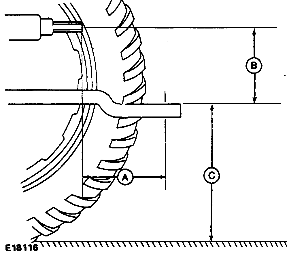
E18116-UN-12SEP88 -
Set drawbar to the following dimensions:
540 rpm
PTO Size
A
mm (in.)
B
mm (in.)
C
mm (in.)
1-3/8 in.
356 (14)
152—305
(6—12)
330—508
(13—20)
To avoid powerline damage when front of tractor “noses” down, there must be a minimum of 90—102 mm (3.5—4.0 in.) clearance (B) between powerline and top of hitch strap (A). Measure on level ground.
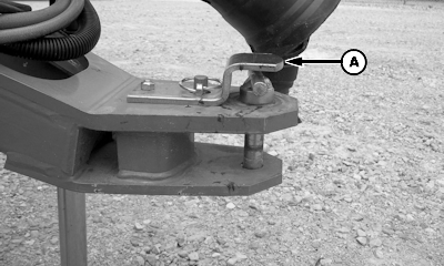
E58840-UN-29JUL10A - Hitch Strap
If tractor drawbar is too low the following problems can occur:- Drag tall windrows
- Feeding capacity is reduced due to feed opening being closed
- Pickup will not raise high enough for transport
- Inadequate pickup float at recommended spring settings
- Slow bale discharge
To increase drawbar height, flip drawbar over (offset up).
If tractor drawbar is too high the following problems can occur:
- Pickup teeth will not touch ground
- Gate may not clear the bale during discharge
|
GW44282,00004F8-19-20150507 |