Replacing and Adjusting Bale Diameter Sensor Mounting Bracket
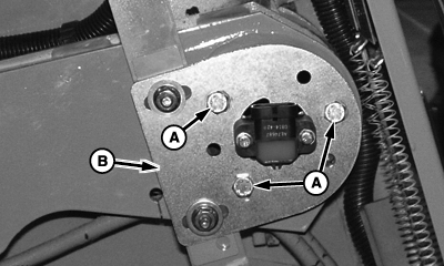
E55822-UN-09JUN08
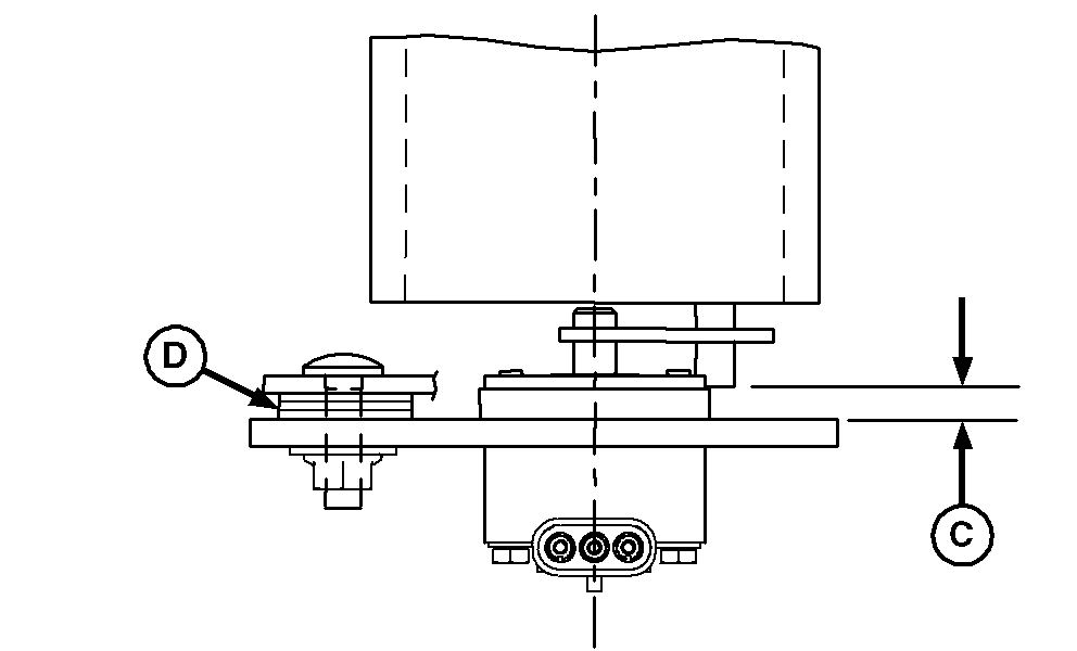
E55850-UN-07JUL08
A - Cap Screws (3 used)
B - Sensor Mounting Bracket
C - Distance
D - Shims
When replacing mounting bracket, or before adjusting the sensor, the mounting bracket must be checked to ensure it is properly centered.
-
Ensure seam in tube does not interfere with cap screws when centering mounting bracket.
Insert three 5/16 x 2.0 in. cap screws (A) into three of the six holes in a triangular pattern on mounting bracket (B) with heads facing out.
-
Fasten cap screws with nuts on back of mounting bracket.
-
Loosen two mounting bolts holding bracket to baler.
-
Adjust bracket (B) so there is equal space between inside of the tube and the three cap screws. Tighten bracket mounting bolts.
-
 Remove the three 5/16 in. cap screws and nuts before
tension arm is moved. Failure to do this, will destroy the mounting
bracket and sensor.
Remove the three 5/16 in. cap screws and nuts before
tension arm is moved. Failure to do this, will destroy the mounting
bracket and sensor. -
With bracket and sensor mounting screws tight, check for specified distance (C) between tension arm tube pin and plate. Add or remove shims (D) to obtain specified distance.
Pin-to-Plate Distance (C) 0.6—10 mm (0.24—0.40 in.) -
Adjust sensor. (See ADJUSTING BALE DIAMETER SENSOR (Channel 005) in this section.)
|
OUO6078,00000B1-19-20090423 |