Install Wheel Spindles
-
Wheel spindles and tires are factory installed in the shipping position on the baler. Change spindles from the shipping position to the normal position.
Do not operate the baler with the wheel spindle in the shipping position.
Wheel spindle position controls the baler height and feeding capacity.
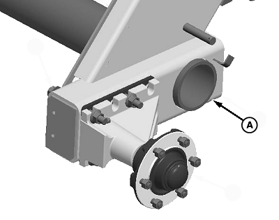
E81543-UN-18JUL16Shipping Configuration
A - Baler Frame
Always place a jackstand or equivalent support under the baler frame (A) when raising the baler.Park baler on a level surface.
-
Using a jack or hoist, raise one side of the baler.
-
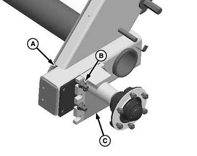
E81544-UN-18JUL16Normal Position
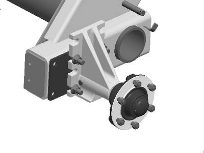
E81545-UN-18JUL16Raised Position
A - Cap Screw, M16 x 180 (4 used)
B - Flange Nut, M16 (4 used)
C - Wheel Spindle Assembly
Remove and retain the cap screws (A), flange nuts (B), and the spindle assembly (C). -
Position the spindle assembly (C) in the normal position as shown.
The raised position is used for certain crop conditions.
-
Install the previously removed cap screws (A) and flange nuts (B).
-
Tighten the flange nuts to specification.
Flange Nuts (B) Torque 237 N•m (175 lb·ft) -
Repeat on the opposite side.
|
SF04007,0000C24-19-20160822 |