Replacing Mower Drive Belt (Z500 Series with 48A, 48HC, 54A, 54HC, 60HC and 62C Mowers)
NOTE: A 48HC deck has been used in the illustrations below. All mower decks listed above use a similar configuration of sheaves.
-
Park machine safely. (See Parking Safely in SAFETY section.)
-
Allow engine and muffler to cool completely.
-
Remove mower deck.
-
Remove deck drive belt as follows:
-
 CAUTION: Avoid injury! Components are installed under spring
tension. Wear eye protection and use proper tools when installing
and removing components with spring tension.
CAUTION: Avoid injury! Components are installed under spring
tension. Wear eye protection and use proper tools when installing
and removing components with spring tension.
Unhook spindle cover (A) torsion spring (B) from wire form on each side of deck.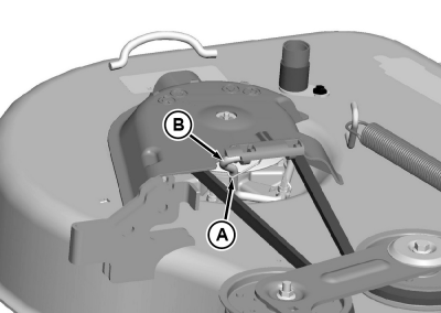
GXT002436-UN-16JUL15 -
Lift each spindle cover (C) to align the wire form index tab with the mating key hole in the cover. Slide each cover forward (D) on wire form to remove from deck.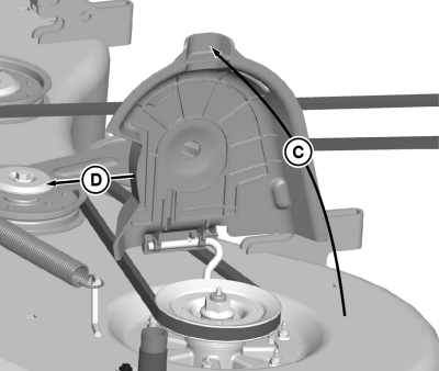
GXT002437-UN-16JUL15 -
Remove spring from welded spring hook (E) on deck.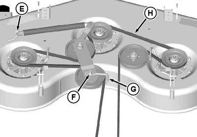
GXT002511-UN-31JUL15 - Remove nut (F) on tension sheave and lower bolt to remove guide (G). Remove belt (H) from all sheaves.
-
-
Inspect belt for wear or damage; replace as necessary.
-
Clean top surface of mower deck and sheaves.
-
Install belt on mower deck as shown.
-
Make sure belt guide (G) is indexed as shown, and tighten nut (F) to specification.
Item Measurement Specification Sheave Nut Torque 47 N·m (35 lb-ft) -
Install spring on welded spring hook (E) on deck.
-
NOTE: Failure to seat belt properly on sheaves may result in belt damage.
Make sure belt is properly seated on all sheaves, and install belt shields:
-
Hold shield perpendicular to deck shell, and place spring between mounting holes.
-
Aligning key hole in shield with index tab on wire form, slide shield, and spring fully onto wire form.
-
Lower shield to deck, and pull curved leg of torsion spring down and around wire form.
-
-
Install mower deck.
|
TH84124,0000213-19-20150731 |