| FM RADIO OUTPUT POWER TO CIRCUIT BREAKER/WIRE GAUGE |
RADIO
OUTPUT
POWER
(WATTS) |
APPROX.
CIRCUIT
PROTECTION
NEEDED a |
CIRCUIT
BREAKER
SIZE AND
PART NO. |
WIRE
SIZE
(AWG)
a |
| Up to 5 b |
- |
- |
- |
| 10 |
5 Amps |
6A - AT41395 |
16 |
| 20 |
10 Amps |
10A - AT42014 |
14 |
| |
|
AR55649 |
|
| 30 |
15 Amps |
15A - AT42040 |
12 |
| 40 |
20 Amps |
20A - AT41394 |
10 |
| 50 |
25 Amps |
25A - AM33621 |
10 |
| 60 c |
30 Amps |
30A - AR49352 |
8 |
| 80 c |
40 Amps |
40A - AT29162 |
8 |
| 100 c |
50 Amps |
50A - AH112189 |
8 |
| aThese are guidelines only. Consult your radio manual for actual values. |
| bMay use the power leads supplied with the machine. If this is not desirable, use the wire and circuit breaker for a 10 watt radio. |
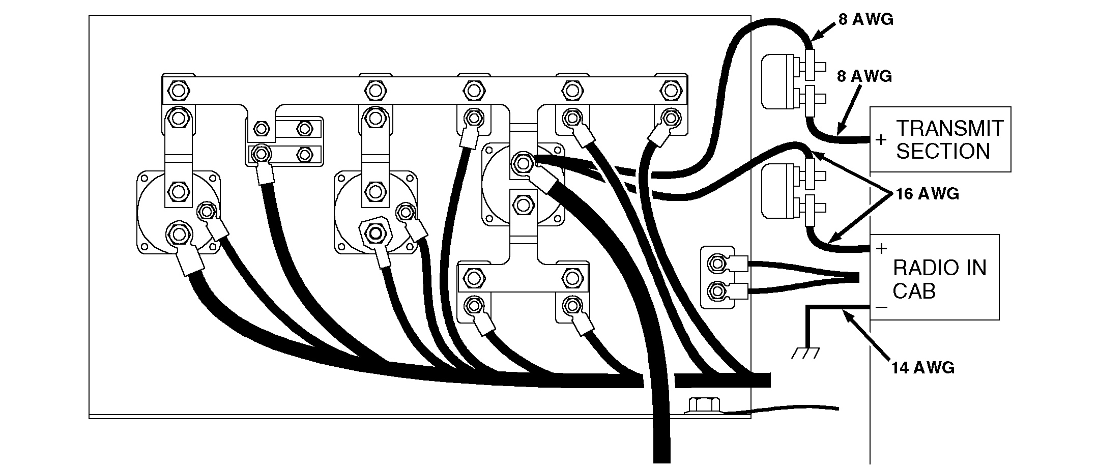
| cIf two input power leads are needed for your radio, the wire size shown is for the transmit section only. Consult your radio manual for the low current requirements. |
|
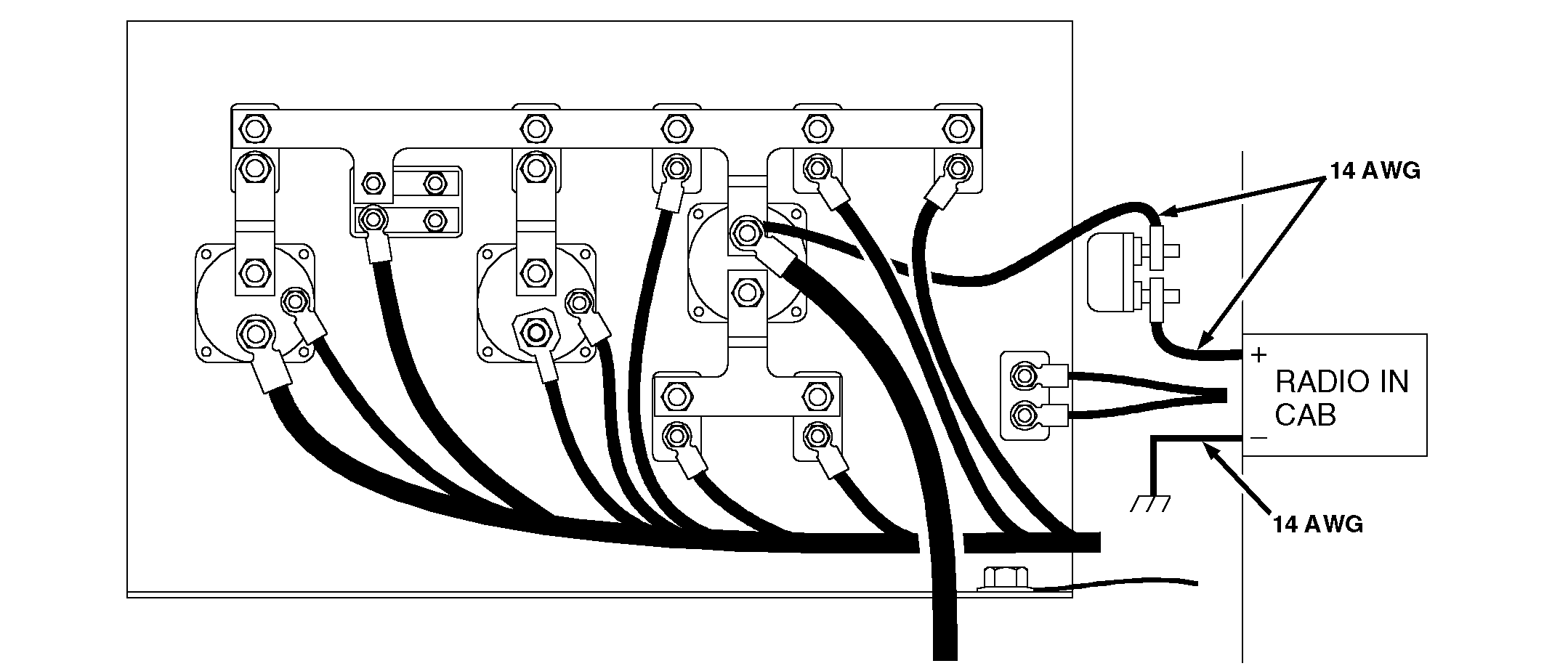
Using the chart, determine the circuit breaker and wire size needed for your radio.
The circuit breakers should be mounted to the side of the relay panel as shown. Due to the different styles available, the circuit breakers mounting feet should be used as a template for drilling the mounting holes. Route the power wire from the circuit breakers through the cab wall connector plate grommet to the radio along side the left main wiring harness.
Use a protective harness covering anywhere that the wire insulation might come into contact with sharp edges.
|

