Rear Axle AdjustmentThe axle is adjustable to let the rear tires track the drive tires.
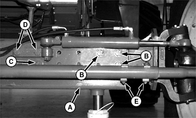
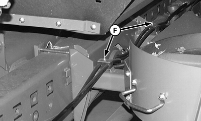
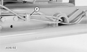
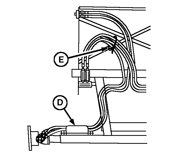
Jack up one end of the axle (A). Remove bolts (B), (C), cylinder bolts (D) and tie rod bolts (E). Loosen power steering hose clamps (F) to adjust hoses. Extra hose must be stored in axle frame. Tighten clamps after moving hoses. If combine is equipped with 4-wheel drive, loosen hose clamp (G) and hose tie strap (H). Pull enough hose through clamp to be able to reposition axle. Tighten clamp and tie strap after moving axle. Refer to the chart and position axle to correct width. Tie rod holes will go in or out the same amount of holes and align correctly. A drift may be needed to align axle holes and start upper bolts (C). Place bolts (B), (C), (D) and (E) back in correct holes. Torque cap screws (B), (C), (D) and (E) to specification. Specification
Specification
|
|
HX,AG,SF7212 -19-04MAR99-1/2 |
|
IMPORTANT: This sequence must be followed because of "relaxing" of the bolts. Repeat steps on other side. Re-torque first side to specification then re-torque second side. |
HX,AG,SF7212 -19-04MAR99-2/2 |
 CAUTION:
When changing axle widths, the rear frame of combine must be raised and blocked properly.


