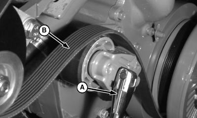
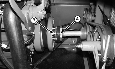
Replace Engine Accessory Drive Belt (9550, 9650 Combines)1. To remove accessory belt, insert a 1/2 inch drive breaker bar (A) into the square hole in idler to release tension on the belt. Remove belt (B) from alternator.
|
|
OUO6075,0000132 -19-01DEC00-1/8 |
|
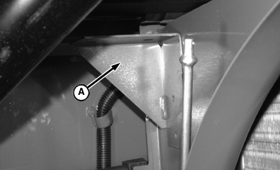
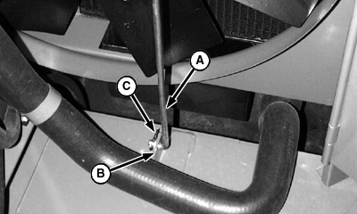
2. Remove spring locking pin from upper rotary screen tension rod and remove rod from bracket (A) to relieve tension on rotary screen drive belt. 3. (9550 Only) Remove rotary screen belt from sheave on engine.
|
|
OUO6075,0000132 -19-01DEC00-2/8 |
|
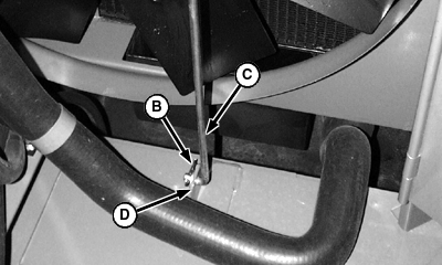
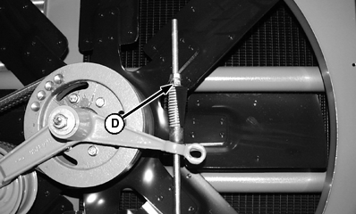
4. Loosen jam nut and adjusting nut (A) 5. Remove spring locking pin (B) and tension rod (C) from bracket (D) to gain access for the removal and installation of fan belt. 6. (9550 Only) Remove fan belt.
|
|
OUO6075,0000132 -19-01DEC00-3/8 |
|
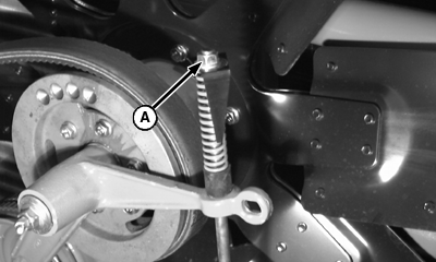
7. (9650 Only) Remove three screws (A) and spacers (B). 8. Remove old accessory drive belt.
|
|
OUO6075,0000132 -19-01DEC00-4/8 |
|
9. Install new belt (B), by inserting a 1/2 inch breaker bar (A) into square hole of idler to release tension.
|
|
OUO6075,0000132 -19-01DEC00-5/8 |
|
10. (9650 Only) Install spacers (B) and tighten screws (A) to specification Specification
|
|
OUO6075,0000132 -19-01DEC00-6/8 |
|
11. (9550 Only) Install fan belt 12. Install tension rod (A) into bracket (B) and retain with spring locking pin (C). 13. Tighten adjusting nut (D) until gauge aligns with rubber bushing and tighten jam nut.
|
|
OUO6075,0000132 -19-01DEC00-7/8 |
|
14. (9550 Only) Install rotary screen belt onto sheave on engine. 15. Install tension rod under bracket (A) and install spring locking pin in upper rotary screen tension rod
|
|
OUO6075,0000132 -19-01DEC00-8/8 |
