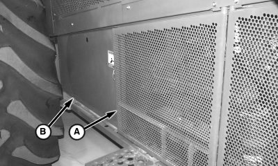
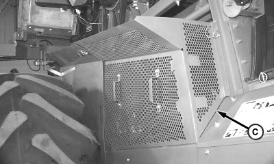
Adjust Concave Level1. Remove spring clip and open side shield (A). 2. Remove spring clips and remove shields (B) and (C).
|
|
OUO6075,00013D8 -19-02FEB01-1/10 |
|
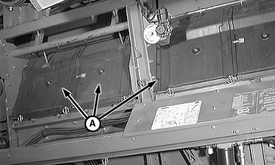
3. Remove separator inspection covers (A).
|
|
OUO6075,00013D8 -19-02FEB01-2/10 |
|
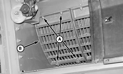
NOTE: Removing separator grate provides access for rotating rotor. 4. Remove cap screws (A) and separator grate (B).
|
|
OUO6075,00013D8 -19-02FEB01-3/10 |
|
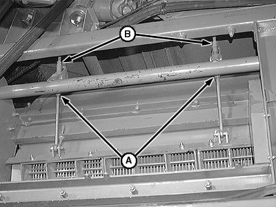
5. Loosen stop bolts (A) and (B).
|
|
OUO6075,00013D8 -19-02FEB01-4/10 |
|
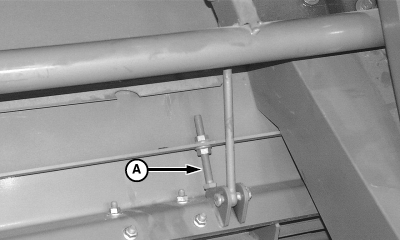
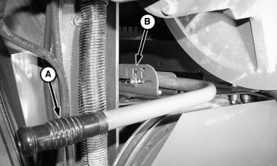
6. Loosen jam nuts (A) and back off nuts (B) five turns each.
|
|
OUO6075,00013D8 -19-02FEB01-5/10 |
|
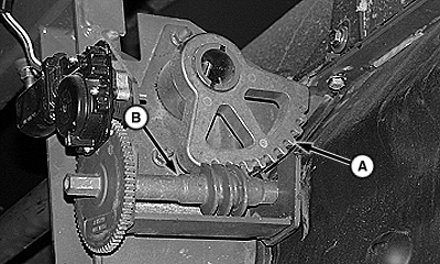
7. Adjust concave all the way up using switch in cab until the worm gear (B) and sector gear (A) are bottomed out in the up position.
|
|
OUO6075,00013D8 -19-02FEB01-6/10 |
|
8. Shift STS Rotor drive gear case using handle (A) to neutral position (B).
|
|
OUO6075,00013D8 -19-02FEB01-7/10 |
|
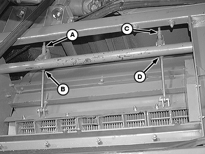
9. Adjust front eye bolt top nut (A) slowly until elements "tick" concave while rotor is rotating. Back off three complete turns. 10. Adjust rear eye bolt top nut (C) slowly, until elements "tick" concave while rotor is rotating. Back off three complete turns. 11. Adjust front eye bolt top nut (A) down slowly until elements "tick" concave. Back off slowly until "tick" stops. As soon as "tick" has stopped back off one complete turn and tighten top jam nut. 12. Adjust rear eye bolt top nut (C) down slowly, until elements "tick" concave. Back off slowly until "tick" stops. As soon as "tick" has stopped back off one complete turn and tighten top jam nut. 13. Tighten bottom front concave adjustment nut. Hold front eye bolt top nut (A) with open end wrench and tighten front eye bolt bottom jam nut (B). 14. Tighten bottom rear concave adjustment nut. Hold front eye bolt top nut (C) with open end wrench and tighten front eye bolt bottom jam nut (D). |
|
OUO6075,00013D8 -19-02FEB01-8/10 |
|
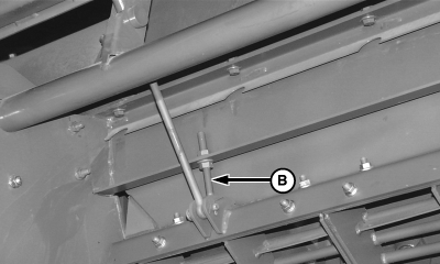
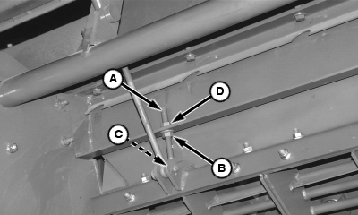
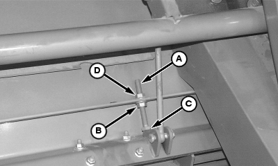
15. Adjust front and rear concave stop bolts (A) by tightening bottom nut (B) until head of bolt (C) is snug against concave. Tighten top nut (D) while holding bottom nut (B) with open end wrench.
|
|
OUO6075,00013D8 -19-02FEB01-9/10 |
|
16. Install separator grate (B) and retain with cap screws (A). 17. Shift STS Rotor drive gear case to desired position. 18. Install separator inspection covers and shields. 19. Calibrate concave position in cab. See CONCAVE SENSOR ZERO CALIBRATION in your combine Operators Manual.
|
|
OUO6075,00013D8 -19-02FEB01-10/10 |