Chopper Blade-Centering
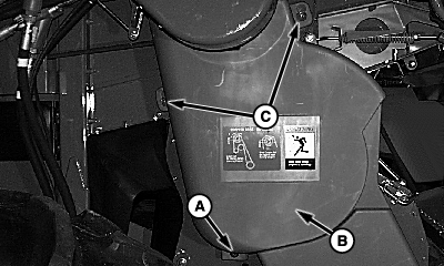
Release latch (A) and lift shield (B) over pins (C). Remove pin (D) from shield (E) and remove shield from bracket (F).
|
|
 CAUTION:
Shut OFF engine, set parking brake and remove key. Before performing service or maintenance on raised chopper, use lift actuator to snap lock-out pins into place.
CAUTION:
Shut OFF engine, set parking brake and remove key. Before performing service or maintenance on raised chopper, use lift actuator to snap lock-out pins into place.
OUO6075,0003A57 -19-13OCT04-1/7 |
|
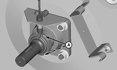
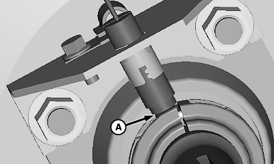
NOTE: It is not necessary to remove sensor completely. Loosen sensor collar screws (A).
|
|
OUO6075,0003A57 -19-13OCT04-2/7 |
|
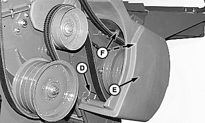
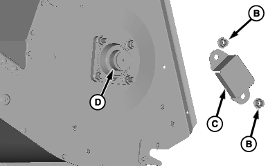
Loosen left-hand side set screw on locking collar (A) and loosen locking collar. Remove and retain nuts (B). Remove and retain bearing shield (C). Loosen right-hand side set screw on locking collar (D) and loosen locking collar.
|
|
OUO6075,0003A57 -19-13OCT04-3/7 |
|
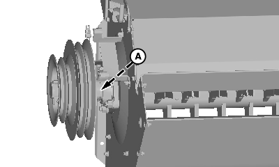
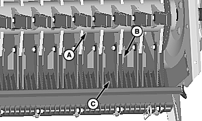
Position chopper rotor (A) to right or left to ensure all rotor blades (B) clear stationary knives (C).
|
|
OUO6075,0003A57 -19-13OCT04-4/7 |
|
Tighten set screws (A) and (D) on both sides in direction of rotor rotation. Install bearing shield (C) on right-hand side and retain with nuts (B).
|
|
OUO6075,0003A57 -19-13OCT04-5/7 |
|
Install and retain sensor using sensor collar screws (A).
|
|
OUO6075,0003A57 -19-13OCT04-6/7 |
|
Measure gap (A) between sensor and sensor collar. Adjust sensor to specifications as needed. Specification
Install chopper shields on left-hand side.
|
|
OUO6075,0003A57 -19-13OCT04-7/7 |