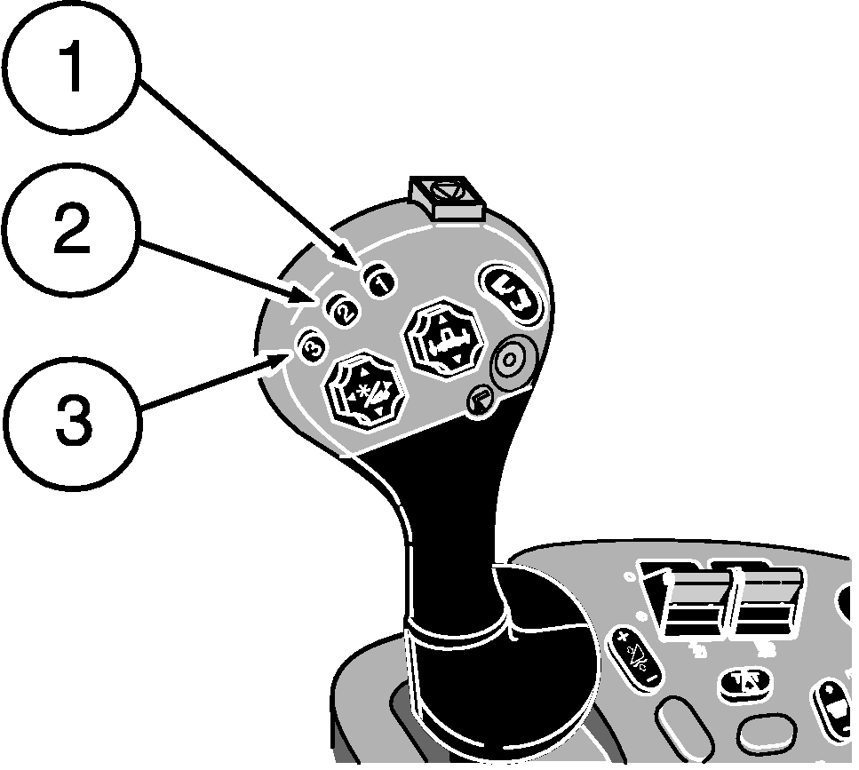
Header Height Sensing-HYDRAFLEX™ PlatformsHeader Height Sensing-HYDRAFLEX allows the operator to adjust the cutterbar ground pressure, or weight of the cutterbar, and return to that setting automatically. HYDRAFLEX works in conjunction with Header Height Sensing to maintain a header position relative to the ground, follow the ground contour, and return to that position automatically. HYDRAFLEX uses a sensor located on the right side of the header to measure the hydraulic pressure used to support the cutterbar. NOTE: HYDRAFLEX does not control cutting height relative to the ground. This is automatically controlled by the height sensing system and is not adjustable through the active header control dial when HYDRAFLEX is present. Header Height Sensing-HYDRAFLEX system must be calibrated when the header is used with the combine for the first time (see Calibration Procedures section). Activation buttons 1, 2 or 3 located on the multifunction control handle are used to select one of three different programmed HYDRAFLEX pressures. NOTE: If both Header Height Resume and Header Height Sensing are enabled, only activation button 1 will activate Header Height Resume, activation buttons 2 and 3 will then be assigned to Header Height Sensing. OperationHeader Height Sensing-HYDRAFLEX will be active when:
|
|
|
HYDRAFLEX is a trademark of Deere & Company | OUO6075,0000396 -19-21APR06-1/2 |
|
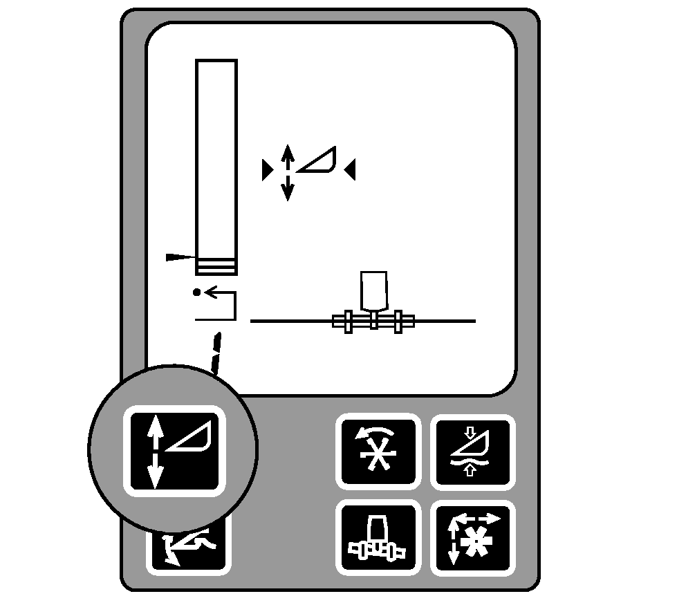
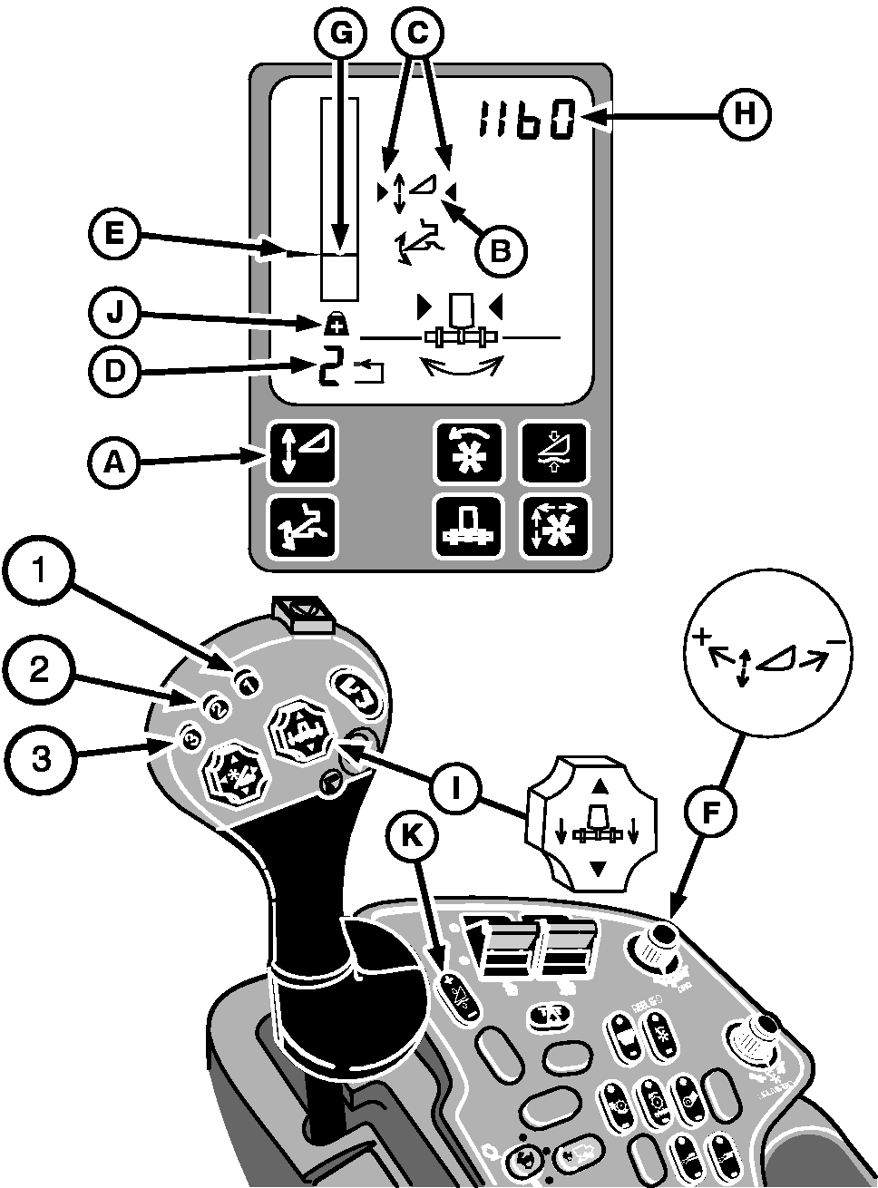
The system is enabled by pressing button (A) on the display. Symbol (B) will appear on the display. Activate Header Height Sensing-HYDRAFLEX by pressing activation buttons 1, 2 or 3 on the multifunction control handle. Arrows symbols (C) indicate the system is active. Weight symbol (J) and pressure display (H) will appear indicating HYDRAFLEX pressure is being monitored during header height sensing. Number (D) in the lower left corner of the display indicates which activation button was selected. To change HYDRAFLEX pressure setpoint indicator (E) for activation buttons, press desired activation button and adjust pressure using active header control dial (F). Pressure setpoint is displayed by an arrow to the left of the bar graph and actual pressure (H) is shown in the upper right side. A single line in bar graph (G) is also displayed to show whether the pressure matches the setpoint indicator. Turn active header height control dial towards plus (+) symbol to increase HYDRAFLEX pressure and setpoint, or towards minus (-) symbol to lower HYDRAFLEX pressure and setpoint. Manually adjusting header height using header lower switch (I) will temporarily override the system until the switch is released. Once released the system will return to the automatic mode. Using header raise switch (I) will temporarily deactivate the system until the header lower switch is pressed. Once pressed the system will reactivate. Press any of the three activation buttons or by manually lowering header height with header lower switch (I) will reactivate the system. Header will move to the selected pressure. The system can be disabled by pressing button (A) on the display. |
|
OUO6075,0000396 -19-21APR06-2/2 |


