Adjusting Row Spacing
|
||||||||||||||||||||||||||||||||||||||||||||||||||||||||||||||||||||||
JK22594,00000BD -19-07AUG06-1/6 |
|
NOTE: 494, 594, 694 and 894 models cannot be set for 1016 mm (40-in.) row spacing.
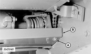
1. Remove and retain attaching hardware (A) and row unit drive shield (B).
|
|
 CAUTION:
When working under the corn head, always place the cylinder safety stop in safety position to prevent header from lowering.
CAUTION:
When working under the corn head, always place the cylinder safety stop in safety position to prevent header from lowering.
JK22594,00000BD -19-07AUG06-2/6 |
|
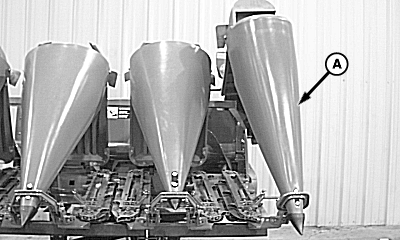
2.
Remove shields and points (A) from row units.
|
|
JK22594,00000BD -19-07AUG06-3/6 |
|
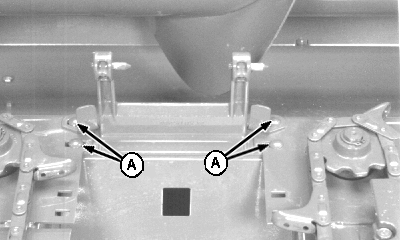
3.
Remove bolts (A) from row unit filler plates and hinge pin brackets.
|
|
JK22594,00000BD -19-07AUG06-4/6 |
|
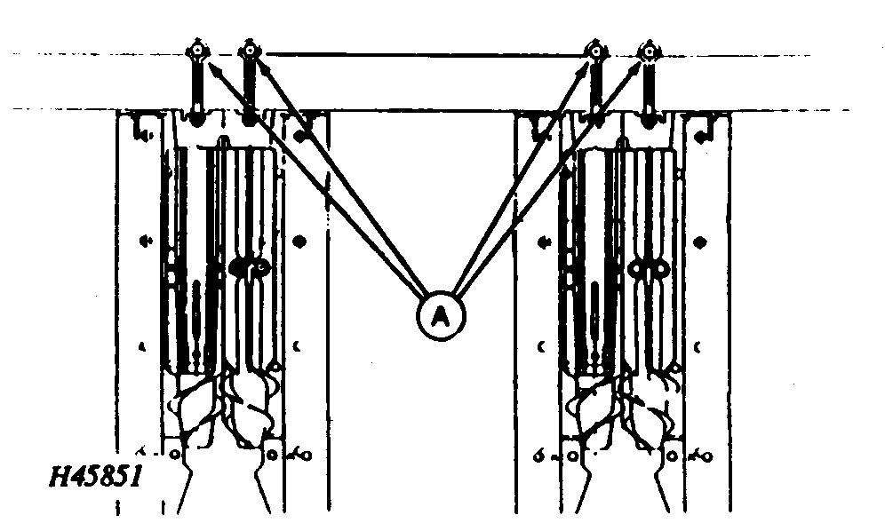
4.
Loosen nuts (A) on attaching bolts of center two row units and move units to correct row spacing then loosen and move next two units and continue until all row units are spaced correctly. Torque unit attaching bolts to specification.
Specification
NOTE: To slide row units to desired location, place a support under row unit skid plates.
|
|
JK22594,00000BD -19-07AUG06-5/6 |
|
5.
Position row unit filler plates and hinge pin brackets for desired row spacing and reinstall bolts (A) in filler plates and brackets.
6. Reinstall shields and points on row units. 7. Reinstall row unit drive shield. 8. Install hydraulic cylinder safety stop in storage position. 9. Start engine and engage corn head.
|
|
JK22594,00000BD -19-07AUG06-6/6 |