Align Knife Head and Knife DriveEfficient cutting performance requires a good cutting edge and proper component alignment. Timely replacement of worn knife guards and sections help maintain good cutting performance while reducing loads and extending the life of drive components. Proper adjustment and alignment of knife guards and drive components also improve cutting performance and reduce system loads. Proper knife head and knife drive alignment is critical in achieving effective cutting performance and drive durability. Improper alignment can cause knife binding at the first guard during knife strokes resulting in: heat build up, accelerated wear, and high knife loads. Those factors greatly affect the life of the knife. Use the following steps to check and adjust knife head and knife drive alignments. |
NS43404,00005F5 -19-09JUN08-1/9 |
|
1.
Raise reel completely and engage safety stops (A) on reel lift cylinders.
2. Support platform with wood blocks under front of frame and under ends of platform behind skid shoes. 3. Set parking brake, shut OFF engine, and remove key. 4. Remove left-hand side shields.
|
|
NS43404,00005F5 -19-09JUN08-2/9 |
|
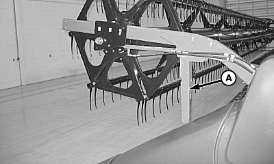
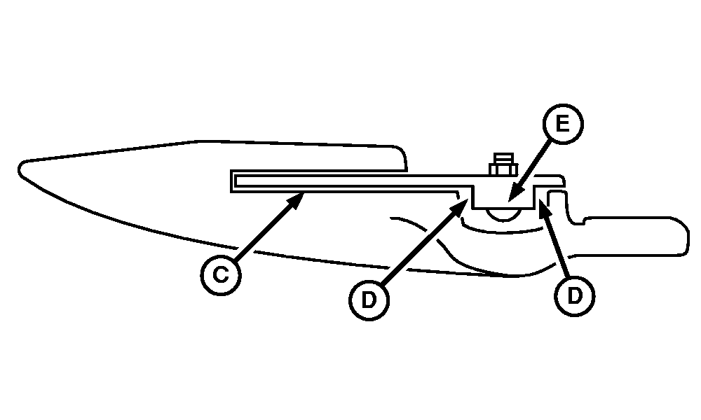
5.
Visually inspect the positions (A and B) of the knife section in the first guard slot and the knife back (C) fore and aft position in the guard. If there is excessive contact in either location, adjust knife head and knife drive alignment.
|
|
NS43404,00005F5 -19-09JUN08-3/9 |
|
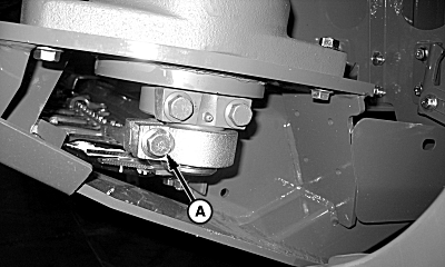
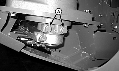
6.
Loosen knife head clamp cap screw (A).
|
|
NS43404,00005F5 -19-09JUN08-4/9 |
|
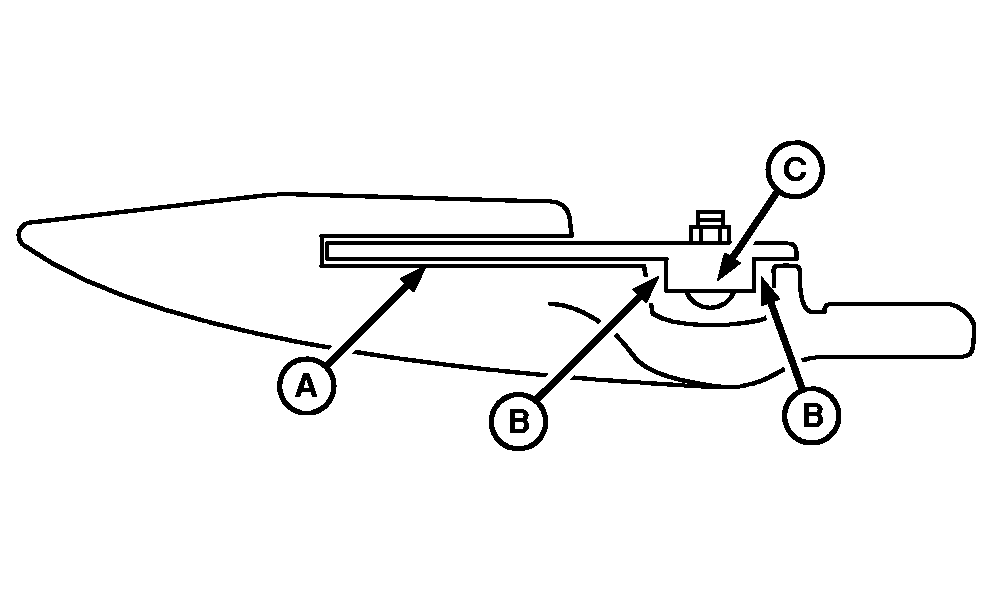
7.
Set vertical position and angle of knife head (A) so cutting surface is: centered in guard slot and is parallel to bottom of guard slot at (C).
NOTE: Make sure knife head (A) does not contact bearing shield (B). 8. Check fore and aft gap distance (D) at both locations between knife back (E) and first guard to ensure that a gap exists. If there is no gap, proceed to reposition the knife gearbox, reset vertical position, and angle of knife section.
|
|
NS43404,00005F5 -19-09JUN08-5/9 |
|
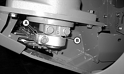
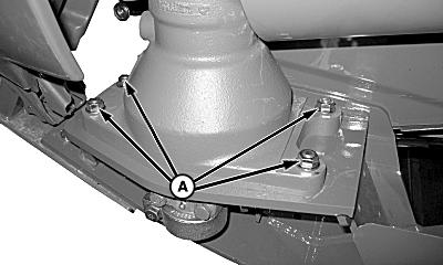
9.
Loosen four gearbox mounting hardware (A).
10. Using rubber mallet, move gearbox as required to achieve proper knife back fore and aft clearance. 11. Tighten nuts to specification. Specification
|
|
NS43404,00005F5 -19-09JUN08-6/9 |
|
12.
Reset vertical position and angle of knife head (A), and check clearance of bearing shield (B), and recheck all clearances. Repeat procedure until proper clearance is achieved.
|
|
NS43404,00005F5 -19-09JUN08-7/9 |
|
NOTE: While tightening cap screws to specification use a pry bar to avoid twisting of the cutterbar head and loss of knife head settings. 13. Tighten cap screws (A) to specification. Specification
14. Verify that the knife section is still properly positioned in the first guard slot after the knife head cap screw is fully tightened.
|
|
NS43404,00005F5 -19-09JUN08-8/9 |
|
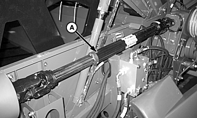
15.
Rotate knife driveshaft (A) making sure there is no binding of cutterbar head, knife sections, or knife shields. If binding occurs repeat adjusting steps.
16. Reinstall side shields.
|
|
NS43404,00005F5 -19-09JUN08-9/9 |