Header Reel/Belt Pickup Pump Belt (Variable Speed Feeder House)-Replacing
Start engine, engage separator and move switch to fast idle. Adjust feeder house drive belt to slow front shaft speed.
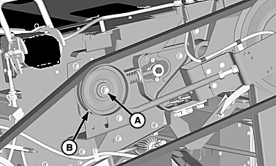
Disengage separator, stop engine, and remove key. Lower safety stop and remove left-hand feeder house shields. Look under rubber boot (A) to verify if upper sheaves are fully open. At low speed position, outer sheave half bulb is against bracket (B). |
|
OUO6075,000000D -19-25JUN08-1/13 |
|
Loosen idler nut (A) and slide sheave (B) down to release tension on drive belt.
|
|
OUO6075,000000D -19-25JUN08-2/13 |
|
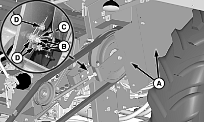
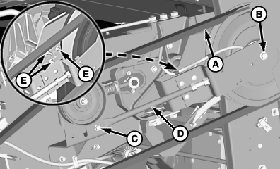
Remove shields (A), nuts (B) and sensor bracket (C). Loosen nuts (D) to allow upper sheave assembly to move.
|
|
OUO6075,000000D -19-25JUN08-3/13 |
|
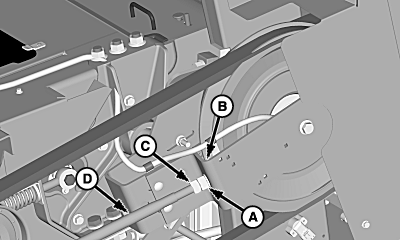
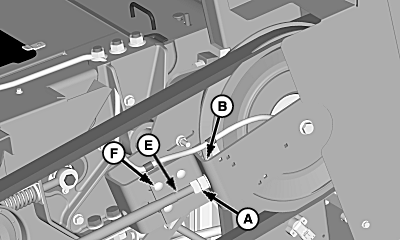
NOTE: Nut (C) must be moved and jammed against nut (A). Together these nuts can be used to turn tensioner bolt. Loosen nut (A) away from bracket (B) until a 3 mm (1/8 in.) gap exists between either side of bracket. Tighten nut (C) against nut (A). NOTE: Threading bolt into tensioner allows sheave to move forward to remove drive belt. Use nut (A) to screw threaded bolt into tensioner (D). |
|
OUO6075,000000D -19-25JUN08-4/13 |
|
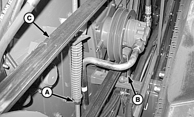
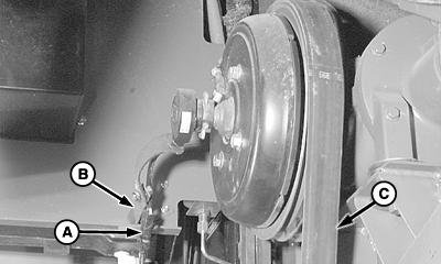
Loosen nuts (A) to relieve tension from drive belt. Remove cap screw and nut to move reel pump brace (B) out of way so drive belt (C) can be removed.
|
|
OUO6075,000000D -19-25JUN08-5/13 |
|
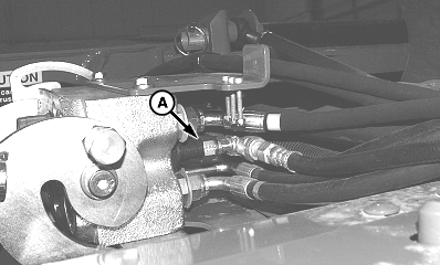
NOTE: Cap hydraulic hose to prevent system contamination and fluid loss. Disconnect hydraulic hose (A) from multi-coupler.
|
|
OUO6075,000000D -19-25JUN08-6/13 |
|
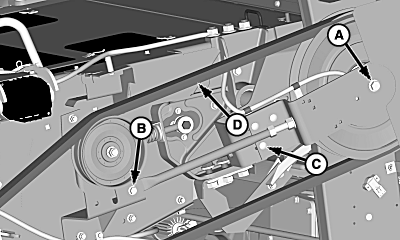
Remove cap screw (A), cap screw and nut (B) and round head bolts (C). Remove drive belt (D) from rear sheave.
|
|
OUO6075,000000D -19-25JUN08-7/13 |
|
Disconnect connector (A) and remove strap from bracket (B). Remove and discard drive belt (C). Install replacement drive belt, connect strap to bracket and connect electrical connector.
|
|
OUO6075,000000D -19-25JUN08-8/13 |
|
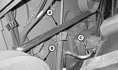
Install drive belt (A) around reel pump and rear sheaves (B). Install previously removed reel pump brace (C) with cap screw and nut.
|
|
OUO6075,000000D -19-25JUN08-9/13 |
|
Install drive belt (A) around rear sheave. Install cap screw (B) and tighten to specification. Specification
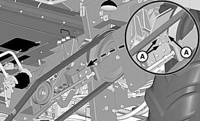
Tighten cap screw and nut (C). Leave round head bolts (D) loose at this time. Tighten nuts (E) to prevent upper sheave assembly from moving. |
|
OUO6075,000000D -19-25JUN08-10/13 |
|
Connect hydraulic hose (A) to multi-coupler.
|
|
OUO6075,000000D -19-25JUN08-11/13 |
|
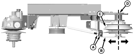
A-Nuts (2 used)
B-Outer Strap
C-Sheave (2 used)
D-Side Sheet
E-Cap Screw
F-Round Head Bolts (3 used)
|
NOTE: Check alignment of upper countershaft sheaves (C). Make sure that sheaves are running parallel to feeder house side sheet. Parallel alignment of countershaft sheaves must be adjusted by loosening round head bolts (F) and using nuts (A) on bolt (E). Using nuts (A), turn bolt (E) to move outer strap (B) forward or rearward to align sheaves (C) parallel to feeder house side sheet (D). Tighten round head bolts (F) to specification. Specification
|
|
OUO6075,000000D -19-25JUN08-12/13 |
|
Loosen previously tightened nuts (A) and refer to Feeder House Variable Speed Belt-Adjusting to set sheave gap.
|
|
OUO6075,000000D -19-25JUN08-13/13 |
 CAUTION:
Lower variable sheave is under spring tension; if belt is removed, it will snap back to a closed position.

