Chaffer/Sieve Elements (Self-Leveling Shoe)-Remove and Install
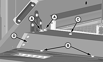
NOTE: It is not necessary to remove straw chopper (if equipped) or spreader (if equipped) to remove chaffer/sieve elements. Chopper or spreader must be in fully raised position. Close chaffer/sieve louvers before removal leveling bays. If louvers are left open, bottom of chaffer bays catch on sieve louvers during removal. 1. Remove cap screws (A-C) and shield (D). |
|
OUO6075,000006E -19-08APR08-1/13 |
|
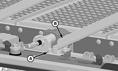
2.
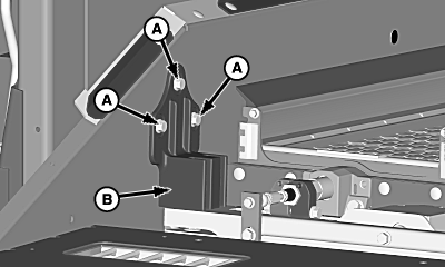
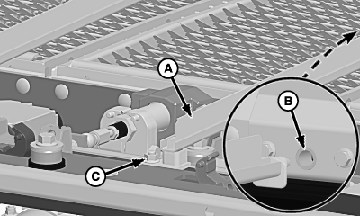
Remove and retain cap screws (A) and side bracket (B) on both sides of machine.
|
|
OUO6075,000006E -19-08APR08-2/13 |
|
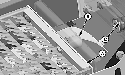
3.
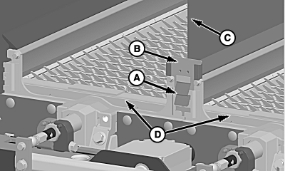
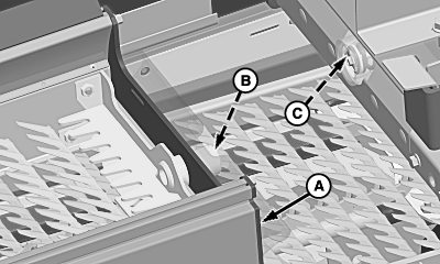
Lift and hold spring (A) and remove divider retainer (B).
4. Slide divider (C) from chaffer bays (D).
|
|
OUO6075,000006E -19-08APR08-3/13 |
|
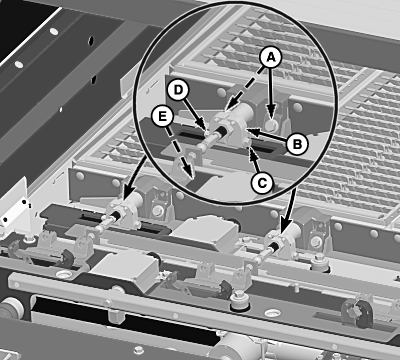
5.
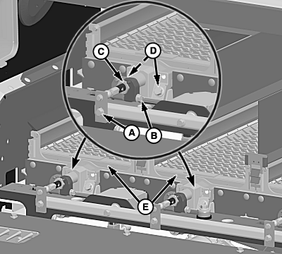
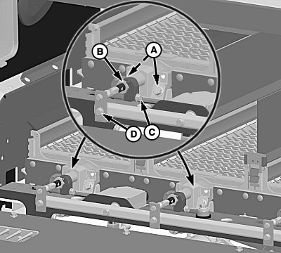
Remove cap screw (A), and cap screw and lock nut (B).
6. Open leveling bay linkages (C). 7. Remove cap screws (D) and slide chaffer bays (E) from guide. 8. Inspect chaffer element and repair or replace as needed.
|
|
OUO6075,000006E -19-08APR08-4/13 |
|
9.
Remove lock nut (A) and bay rail (B).
|
|
OUO6075,000006E -19-08APR08-5/13 |
|
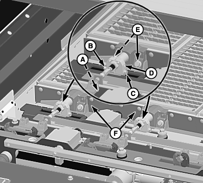
NOTE: If sieve bay must be removed, two chaffer bays must be removed to allow for room. 10. Remove cap screw (A), lock nut (B) and cap screw (C). 11. Open leveling bay linkages (D). 12. Remove cap screws (E) and slide sieve bays (F) from guide. 13. Inspect sieve element and repair or replace as needed.
|
|
OUO6075,000006E -19-08APR08-6/13 |
|
14.
Align sieve bay (A) with guides and slide towards front of machine until pivot (B) aligns with bushing (C).
|
|
OUO6075,000006E -19-08APR08-7/13 |
|
NOTE: Push bay forward to compress spring in bushing area to ensure that bay front lines up properly with bushing. 15. Install and tighten cap screws (A) to specification. Specification
16. Align leveling linkage arms (B) around bay hex shaft. 17. Install cap screw (C) and tighten nut (D) to specification. Specification
18. Align louver opening adjust strap with remote shoe adjust linkage bar and tighten cap screw (E) to specification. Specification
|
|
OUO6075,000006E -19-08APR08-8/13 |
|
19.
Align bay rail (A) with hole (B) and retain with lock nut (C).
|
|
OUO6075,000006E -19-08APR08-9/13 |
|
20.
Align chaffer bay (A) with guides and slide towards front of machine until pivot (B) aligns with bushing (C).
|
|
OUO6075,000006E -19-08APR08-10/13 |
|
NOTE: Push bay forward to compress spring in bushing area to ensure that bay front lines up properly with bushing. 21. Install and tighten cap screws (A) to specification. Specification
22. Align leveling linkage arms (B) around bay hex shaft. 23. Install cap screw and tighten lock nut (C) to specification. Specification
24. Align louver opening adjust strap with remote shoe adjust linkage bar and tighten cap screw (D) to specification. Specification
|
|
OUO6075,000006E -19-08APR08-11/13 |
|
25.
Install divider (C) between chaffer bays (D).
26. Install divider retainer (B) in grooves and push down until spring (A) snaps into place.
|
|
OUO6075,000006E -19-08APR08-12/13 |
|
27.
Install side bracket (B) and tighten cap screws (A) to specification on both sides of machine.
Specification
28. Install previously removed shield and retain with cap screws. 29. Calibrate chaffer/sieve, see Calibration Procedures section. 30. Lower straw spreader or chopper. |
|
OUO6075,000006E -19-08APR08-13/13 |
 CAUTION:
Shut OFF engine, set parking brake and remove key to help prevent accidental starting and personal injury.
