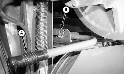
Concave Sections-Remove and InstallNOTE: For ease of removal, close concave completely. 1. Move handle (A) to shift rotor gearcase in neutral position (B).
|
|
OUO6075,000074C -19-25JUN08-1/21 |
|
2.
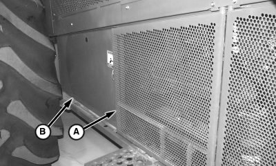
Remove quick-lock pins and open side shield (A).
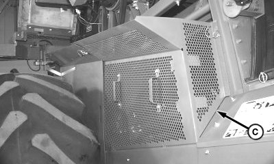
3. Remove quick-lock pins and shields (B and C).
|
|
OUO6075,000074C -19-25JUN08-2/21 |
|
4.
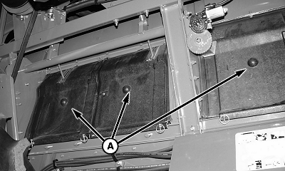
Remove separator inspection covers (A).
5. Inspect wear on concave sections using AH204933 Clearance Gauge.
|
|
OUO6075,000074C -19-25JUN08-3/21 |
|
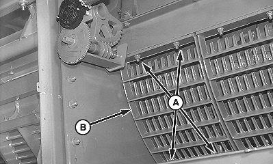
NOTE: Removing separator grate provides access for rotating rotor for maximum concave to threshing element clearance. 6. Remove cap screws (A) and separator grate (B).
|
|
OUO6075,000074C -19-25JUN08-4/21 |
|
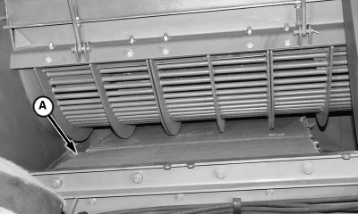
7.
Loosen cap screws (A) and remove left-hand sheet metal diverter (B).
|
|
OUO6075,000074C -19-25JUN08-5/21 |
|
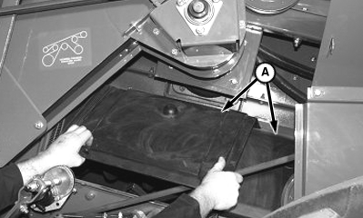
8.
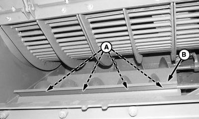
Place a piece of cardboard (A) or poly over conveyor augers. This provides protection for the augers and allows a smooth surface to remove the concaves.
|
|
OUO6075,000074C -19-25JUN08-6/21 |
|
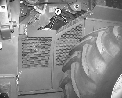
9.
Remove quick-lock pins and shields (A).
|
|
OUO6075,000074C -19-25JUN08-7/21 |
|
10.
Remove quick-lock pins and front two separator covers (A) on right-hand side of machine.
|
|
OUO6075,000074C -19-25JUN08-8/21 |
|
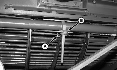
11.
Remove spring lock pin (A) from concave retainer (B).
12. Lift concave retainer and remove handle from each concave section.
|
|
OUO6075,000074C -19-25JUN08-9/21 |
|
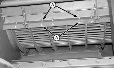
13.
Loosen cap screws (A).
14. Fully open concave. This allows weight of concaves to rest on conveyor auger bed.
|
|
OUO6075,000074C -19-25JUN08-10/21 |
|
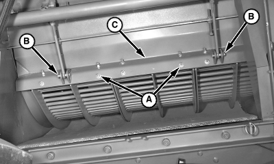
15.
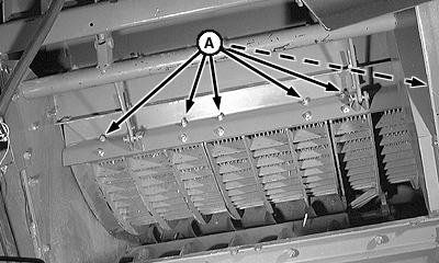
Remove cap screws (A).
16. Remove cotter pins, pins (B) and "Z" bar (C). 17. Rotate rotor such that a gap in the threshing element pattern occurs at mid concave. 18. Remove center concave section. 19. Slide rear concave to the center position and remove. 20. Slide front concave to the center position and remove. 21. Install concaves in reverse order. |
|
OUO6075,000074C -19-25JUN08-11/21 |
|
22.
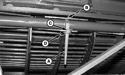
Install concave handle (A) into groove (B) on concave sections.
23. Install concave retainer (C) and retain with spring pin (D).
|
|
OUO6075,000074C -19-25JUN08-12/21 |
|
24.
Position "Z" bar (C) over end of concaves and install cap screws, but do not tighten.
25. Install pins (B). 26. Fully close concave.
|
|
OUO6075,000074C -19-25JUN08-13/21 |
|
27.
Be sure the ends of concaves fit snug into "Z" bar; then tighten top row of cap screws (A) first.
28. Tighten bottom row of cap screws last. 29. Adjust concave level. (See Concave Leveling later in this section.)
|
|
OUO6075,000074C -19-25JUN08-14/21 |
|
NOTE: Make sure top edge of separator cover is under clips. 30. Install separator covers (A).
|
|
OUO6075,000074C -19-25JUN08-15/21 |
|
31.
Install shields (A).
|
|
OUO6075,000074C -19-25JUN08-16/21 |
|
32.
Install separator grate (B) and retain with cap screws (A).
|
|
OUO6075,000074C -19-25JUN08-17/21 |
|
33.
Remove cardboard (A) or poly from conveyor augers.
|
|
OUO6075,000074C -19-25JUN08-18/21 |
|
34.
Install diverter (B) to original position and tighten cap screws (A).
|
|
OUO6075,000074C -19-25JUN08-19/21 |
|
35.
Install separator inspection covers (A).
|
|
OUO6075,000074C -19-25JUN08-20/21 |
|
36.
Install shields (B and C).
37. Close side shield (A). 38. Place rotor drive gearcase in desired speed range.
|
|
OUO6075,000074C -19-25JUN08-21/21 |
