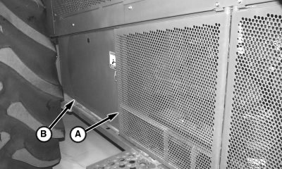
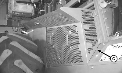
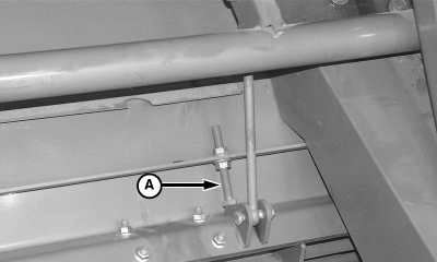
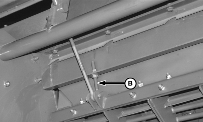
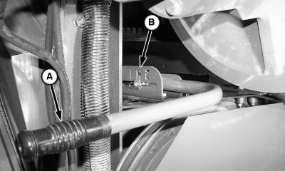
Concave LevelingNOTE: Round bar concave covers (if installed) should be removed prior to beginning concave leveling. 1. Remove quick-lock pins and open side shield (A). 2. Remove quick-lock pins and remove shields (B and C).
|
|
OUO6075,0000D34 -19-25JUN08-1/10 |
|
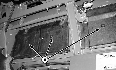
3.
Remove separator inspection covers (A).
|
|
OUO6075,0000D34 -19-25JUN08-2/10 |
|
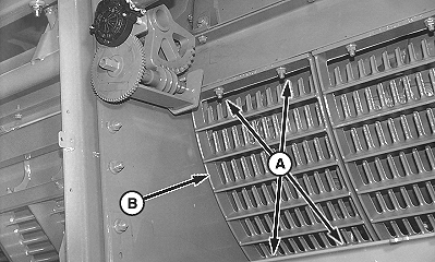
NOTE: Removing separator grate provides access for rotating rotor. 4. Remove cap screws (A) and separator grate (B).
|
|
OUO6075,0000D34 -19-25JUN08-3/10 |
|
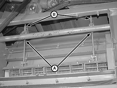
5.
Back off stop bolts (A and B).
|
|
OUO6075,0000D34 -19-25JUN08-4/10 |
|
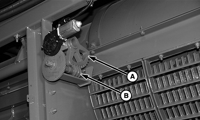
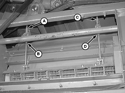
6.
Loosen jam nuts (A) and back off nuts (B) five turns each.
|
|
OUO6075,0000D34 -19-25JUN08-5/10 |
|
7.
Use concave adjust switch to adjust concave up until worm gear (B) and sector gear (A) are bottomed out in the up position.
|
|
OUO6075,0000D34 -19-25JUN08-6/10 |
|
8.
Shift rotor drive gearcase to neutral position (B) using handle (A).
|
|
OUO6075,0000D34 -19-25JUN08-7/10 |
|
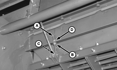
9.
Adjust front eyebolt top nut (A) slowly until elements "tick" concave while rotor is rotating. Back off three complete turns.
10. Adjust rear eyebolt top nut (C) slowly, until elements "tick" concave while rotor is rotating. Back off three complete turns. 11. Adjust front eyebolt top nut (A) down slowly until elements "tick" concave. Back off slowly until "tick" stops. As soon as "tick" has stopped back off one complete turn and tighten top jam nut. 12. Adjust rear eyebolt top nut (C) down slowly, until elements "tick" concave. Back off slowly until "tick" stops. As soon as "tick" has stopped back off one complete turn and tighten top jam nut. 13. Tighten bottom front concave adjustment nut. Hold front eyebolt top nut (A) with open end wrench and tighten front eyebolt bottom jam nut (B). 14. Tighten bottom rear concave adjustment nut. Hold rear eyebolt top nut (C) with open end wrench and tighten rear eyebolt bottom jam nut (D). |
|
OUO6075,0000D34 -19-25JUN08-8/10 |
|
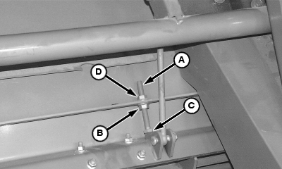
15.
Adjust front and rear concave stop bolt (A) by tightening bottom nut (B) until head of bolt (C) is snug against concave. Tighten top nut (D) while holding bottom nut (B) with open end wrench.
|
|
OUO6075,0000D34 -19-25JUN08-9/10 |
|
16.
Install separator grate (B) and retain with cap screws (A).
17. Shift rotor drive gearcase to desired position. 18. Install separator inspection covers and shields. 19. Calibrate concave position from inside cab. (See Calibration Procedures section.)
|
|
OUO6075,0000D34 -19-25JUN08-10/10 |