Chopper Blades—Replacing and Configuration
 CAUTION: Shut OFF engine, set parking brake and remove key. Before performing service or maintenance on raised chopper, use lift actuator to snap lock-out pins into place.
NOTE: Rotor shown illustrates blade replacement examples for both scoop and paddle blades. Always maintain original factory provided blade pattern.
H87277-UN-06AUG07
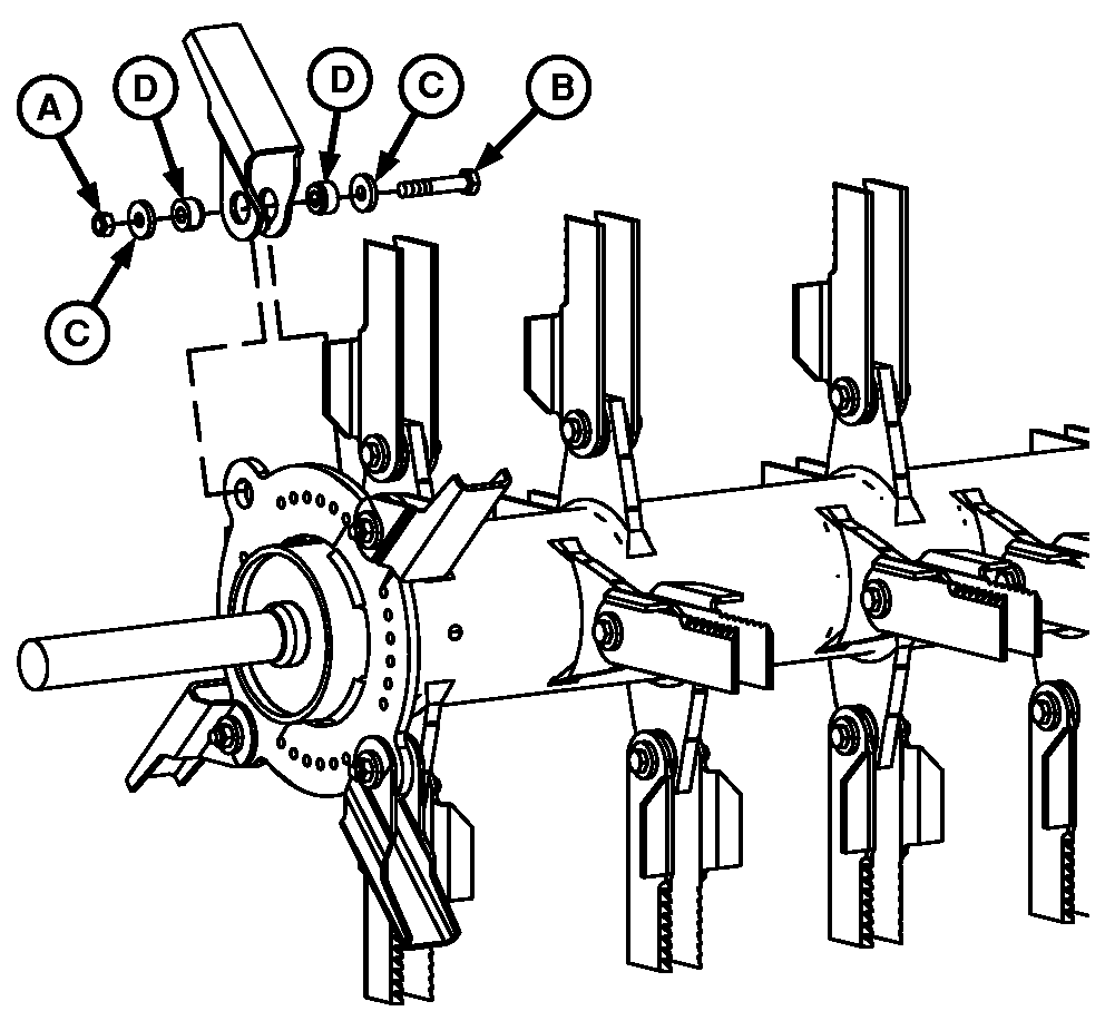
A - Lock Nut
B - Cap Screw
C - Washers
D - Bushings
Outer Blade Removal:NOTE: If removing blades or bushings for inspection purposes, be certain to reinstall blades on SAME support from which they were removed. This must be done to maintain balance. It is a good practice to individually mark each blade before removal.
Remove lock nut (A), cap screw (B), washers (C) and bushings (D).
Inspect and if needed replace blade bushings (D) while replacing blades. See your John Deere dealer for replacement parts.
H87278-UN-03AUG07
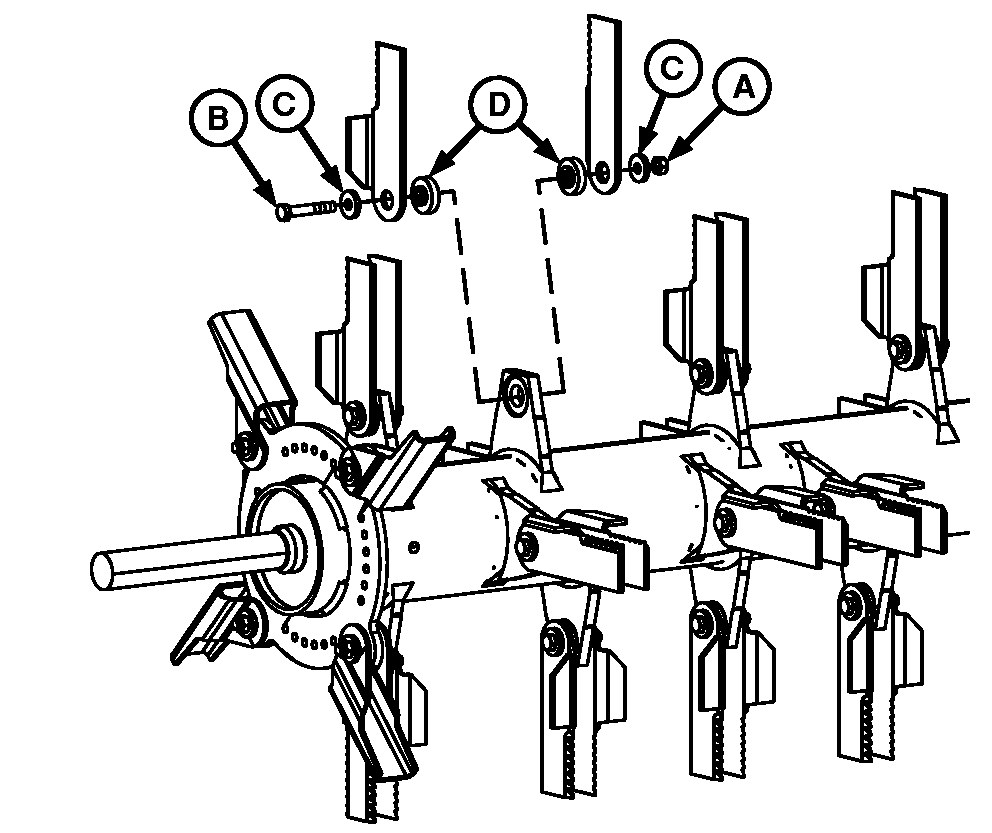
A - Lock Nut
B - Cap Screw
C - Washers
D - Bushings
Inner Blade Removal:NOTE: If removing blades or bushings for inspection purposes, be certain to reinstall blades on SAME support from which they were removed. This must be done to maintain balance. It is a good practice to individually mark each blade before removal.
Remove lock nut (A), cap screw (B), washers (C), and bushings (D).
Inspect and if needed replace blade bushings (D) while replacing blades. See your John Deere dealer for replacement parts.
H87279-UN-03AUG07
H87280-UN-03AUG07
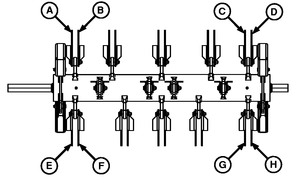
A—H - Paddle Blades
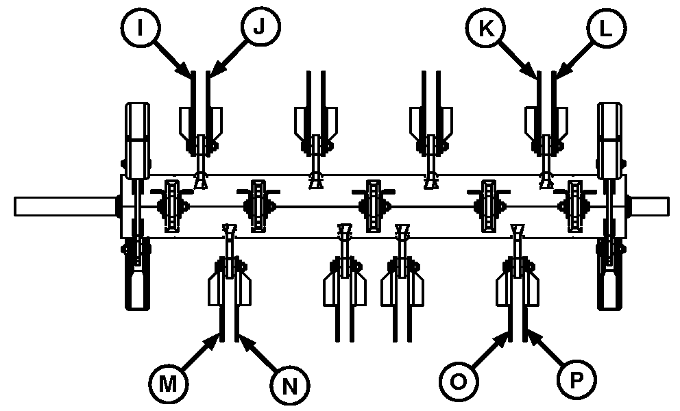
I—P - Paddle Blades
Blade Configuration:IMPORTANT: Chopper balance MUST be maintained. Replace BOTH blades on single support and BOTH blades on opposite support (180 degrees). Also replace four blades at opposite end of rotor, at same axial distance from balance ring. Eight blades MUST be installed to replace one broken blade, or all blades can be replaced at one time. This MUST be done to maintain balance.
If blade (A) is broken, replace blades (A—H).
If blade (I) is broken, replace blades (I—P).
H87277-UN-06AUG07
A - Lock Nut
B - Cap Screw
C - Washer
D - Bushing
Outer Blade Installation:Replace blade and install cap screw (B), washers (C), bushings (D) and lock nut (A). Tighten nuts to specification.
| Item | Measurement | Specification |
| Chopper Blade Lock Nuts | Torque | 60 N·m (44 lb-ft) |
H87278-UN-03AUG07
A - Lock Nut
B - Cap Screw
C - Washers
D - Bushings
Inner Blade Installation:Replace blade and install cap screw (B), washers (C), bushings (D) and lock nut (A). Tighten nuts to specification.
| Item | Measurement | Specification |
| Chopper Blade Lock Nuts | Torque | 60 N·m (44 lb-ft) |
OUO6075,0000A6D-19-20070808 |