Solution System With Load Command
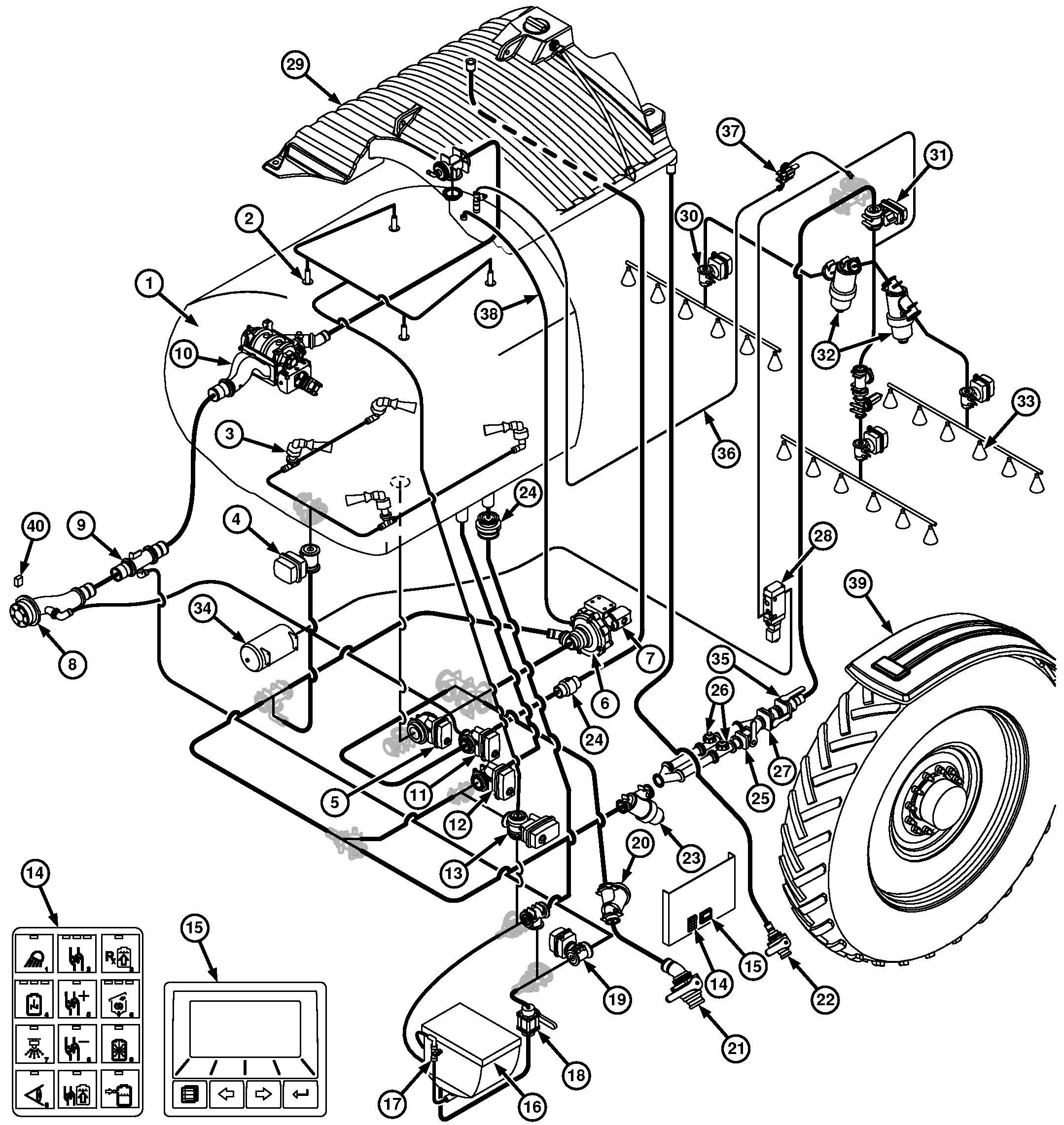
N107967-UN-16JAN14
1 - Solution Tank
2 - Solution Tank Rinse Nozzle
3 - Solution Tank Agitation Nozzle
4 - Agitation Valve
5 - Solution Tank Sump Valve
6 - Centrifugal Pump
7 - Hydraulic Motor
8 - Load Command Sprayer Coupler
9 - Load Command Evacuation Fitting
10 - Load Command Pump
11 - Rinse Tank Sump Valve
12 - Bypass Valve
13 - Eductor/Tank Rinse Valve
14 - Solution Command Keypad
15 - Solution Command Micro Display
16 - Eductor Hopper
17 - Eductor Hopper Rinse Valve
18 - Eductor Hopper Sump Valve
19 - Eductor Venturi
20 - Suction Strainer (20 Mesh)
21 - Side Quik-Fill™ Valve
22 - Rinse Tank Quik-Fill™ Valve
23 - Pressure Strainer (50 Mesh)
24 - Check Valve
25 - High Flow Valve
26 - Solution Flowmeter
27 - Orifice Valve
28 - Boom Air Purge Valve
29 - Rinse Tank
30 - Spray Section Valve
31 - Boom Isolation Valve
32 - Boom Strainer (80 Mesh)
33 - Spray Nozzle
34 - Air Tank
35 - Flowmeter Shutoff Valve
36 - Boom Air Bleed Line
37 - Boom Air Bleed Valve
38 - Solution Pump Bleed Line
39 - Wheel Speed Sensor
40 - Load Command Enable Switch
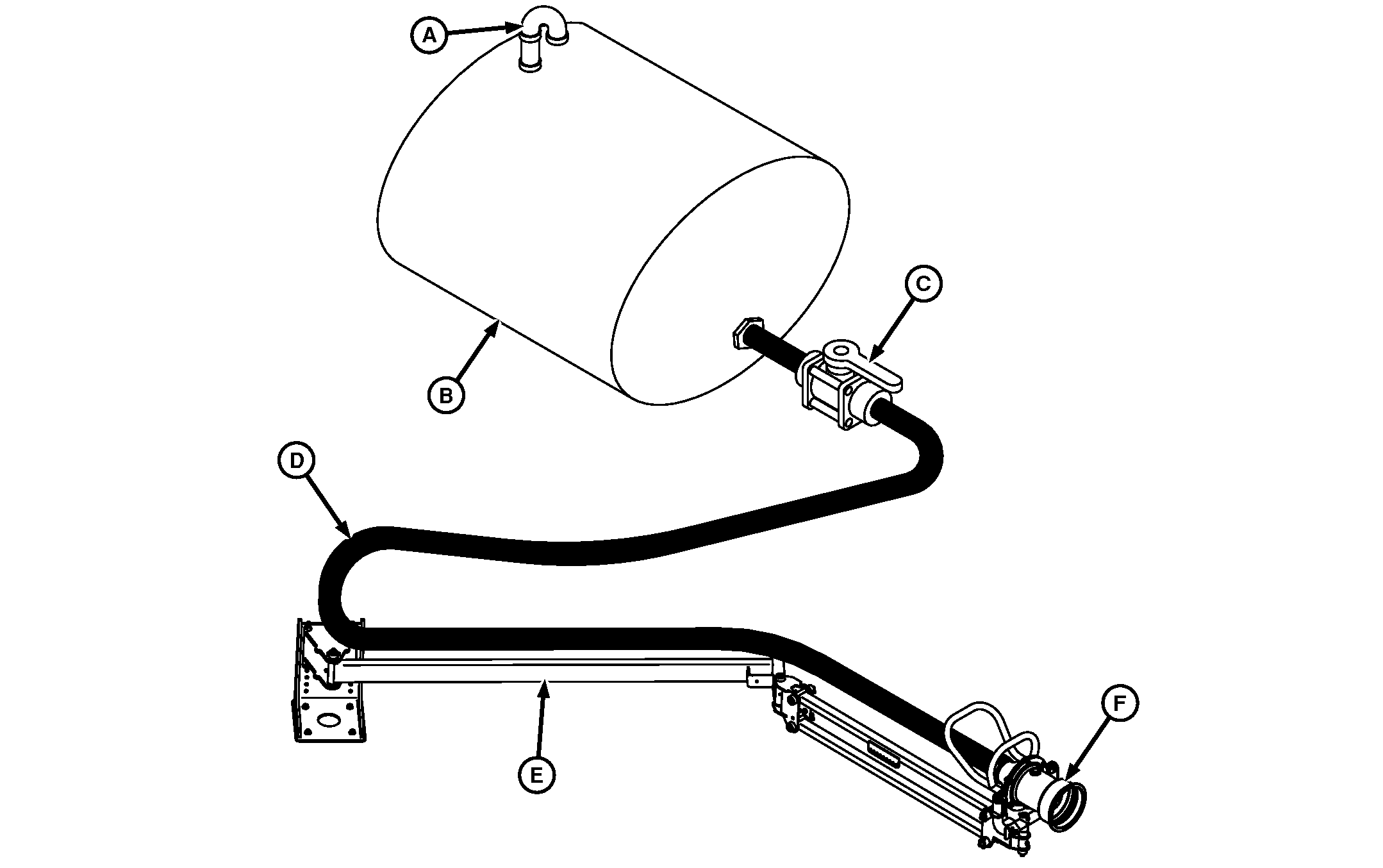
N84232-UN-16APR09
A - Nurse Tank Vent
B - Nurse Tank
C - Shut-off Valve
D - Hose/Line
E - Nurse Arm
F - Nurse Arm Coupler
Load Command™ System Overview
The nurse vehicle supports the sprayer vehicle by hauling and supplying fluid to it. The Load Command system provides the means of controlling the loading process from the nurse vehicle to the sprayer.
Components common to nurse vehicles include the nurse tank (B), nurse tank vent (A) and tank bulkhead/outlet fitting. Components added to a nurse vehicle for Load Command include a nurse arm (E), nurse arm coupler (F), shut-off valve (C), and hoses/lines (D) running between nurse tank and nurse arm coupler. The nurse tank vent allows air to replace fluid during loading to prevent tank damage and provide optimal performance. The shut-off valve provides a method of closing the flow to the nurse arm coupler. The nurse arm supports the nurse arm coupler and plumbing to allow connection to the sprayer.
Components on the sprayer vehicle include the Load Command sprayer coupler (8), Load Command pump (10), and solution tank (1). The sprayer coupler and nurse arm coupler provide the connection point between the two vehicles. The Load Command pump pulls fluid from the nurse vehicle tank to push it into the solution tank.
The loading process begins with the operator driving the sprayer to the nurse vehicle within range of the nurse arm. After parking the sprayer with the engine running, the operator unfolds the nurse arm and presses the arming/shut-off switches. When the switch is armed, the system is ready to start loading but can be turned off at any time. Next, the operator connects the nurse arm and sprayer couplers to start the load sequence. Two proximity sensors detect the connection and the load cycle begins.
The loading sequence begins with the air seal valve providing air to inflate the air seal. The air seal holds the couplers together to allow the operator to release the nurse arm. The engine RPM ramps up and the Load Command valve provides hydraulic fluid to extend the coupler cylinder.
As the cylinder extends it forces the coupler poppet out and pushes against a spring return poppet in the nurse coupler to open a flow path between the two couplers. The Load Command valve directs hydraulic fluid to the hydraulic motor powering the Load Command pump and moves fluid from the nurse tank into the solution tank. Because the Load Command valve can only control one pump at a time, the centrifugal pump (6) cannot be used with the Load Command pump.
During loading the system monitors the pump cavitation and speed sensors. The system will warn the operator of a restriction in the plumbing between the pump and nurse tank. If the pump begins to cavitate excessively due to plumbing restriction, the pump will slow until cavitation reaches an acceptable level. The system also monitors the proximity sensors at the couplers and shuts off if the couplers disconnect.
The solution tank includes three switches to monitor the tank level. The 265 L (70 gal) switch increases the pump to full speed. The 4353 L (1150 gal) switch slows the pump. The 4542 L (1200 gal) switch initiates the system shutdown sequence. This sequence slows the pump to off and closes the coupler poppet. Once closed, the air seal deflates to unlock the couplers. The nurse arm falls away after the couplers unlock or when the sprayer backs away to complete the load process.
After loading, the operator can use the evacuation cycle to recover remaining product in the Load Command lines and put it in the solution tank. Fluid can be evacuated automatically after every load or manually when needed. During the evacuation cycle the centrifugal spray pump draws fluid from the solution tank through the eductor/tank rinse valve (13) and through the eductor venturi (19). The evacuation valve opens to the eductor line, creating a vacuum that sucks the fluid from the Load Command lines to the solution tank. The evacuation cycle will not work when the solution tank is completely empty.
The rinse cycle allows the operator to rinse Load Command lines with fluid from the fresh water tank. During rinsing the rinse tank sump valve (11) opens the Load Command lines to the rinse tank (29). The load pump moves fluid from the rinse tank to the solution tank, allowing rinsing through the Load Command lines via the coupler rinse port. An evacuation cycle will occur during the rinse cycle recovering remaining rinse fluid from the Load Command lines moving into the solution tank.
|
Quik-Fill is a trademark of Deere & Company Quik-Fill is a trademark of Deere & Company Load Command is a trademark of Deere & Company |
OUO6092,000098C-19-20150407 |