Replace Rolling Basket Split Tension Bushings
-
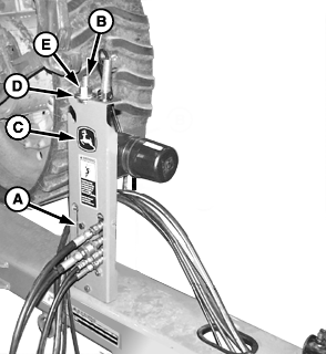
N70708-UN-19AUG05A - Nut and Bolt
B - Tool, 7/8 x 18-1/2 in
C - Operator's Manual Holder
D - Flanged Washer
E - Nut, 7/8 in.
Remove nut and bolt (A) and retain. -
Remove 7/8 x 18-1/2 in tool (B), flanged washer (D), and nut (E) from Operator's Manual holder (C).
-
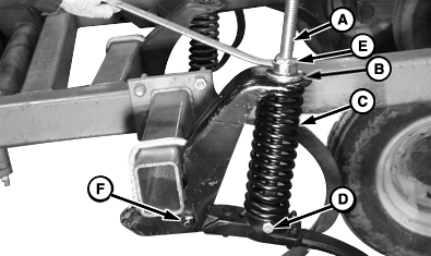
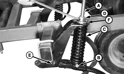
N55329-UN-16OCT00A - Tool, 7/8 x 18-1/2 in
B - Flanged Washer
C - Spring
D - Bolt and Nut, 1/2 x 5 in
E - Nut, 7/8 in
F - Pivot Bolt
Insert 7/8 x 18-1/2 in tool (A) with flanged washer (B) and nut (E) directly through middle of standard tension spring (C), aligning bolt hole at bottom end of tool with bottom hole in standard spring plate. -
Retain tool to bottom end of tension spring plate using bolt and nut (D) removed from operator's manual holder plate.
-
 CAUTION: Spring (C) is strongly compressed. Do not attempt to
loosen or remove spring without using spring compression tool provided
with machine. Loosening or removing spring without using tool can
cause serious injury to yourself or others.
CAUTION: Spring (C) is strongly compressed. Do not attempt to
loosen or remove spring without using spring compression tool provided
with machine. Loosening or removing spring without using tool can
cause serious injury to yourself or others. NOTE: To keep nut (E) turning freely lubricate threads periodically while using this tool.
Compress spring (C) by turning nut (E) clockwise until tension is off pivot bolt (F).
-
Remove pivot bolt (F).
-
Remove chrome bushing (not shown).
-
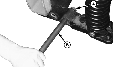
N52319-UN-14FEB00A - Split-tension Bushing
B - Round Stock, 22 mm (7/8 in)
Drive out old split-tension bushing (A) with 22 mm (7/8 in) round stock (B). -
IMPORTANT: Avoid unnecessary bushing wear. Install bushing split (A) within 45° radius, as shown.
Bushing must not protrude from either side of shank.
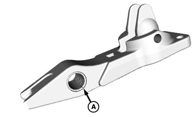
N110976-UN-09APR14A - Bushing Split Location
Install new split-tension bushing (A) with 22 mm (7/8 in) round stock.
-
Install chrome bushing (not shown).
-
N55330-UN-16OCT00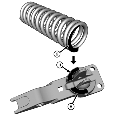
N110978-UN-26MAR14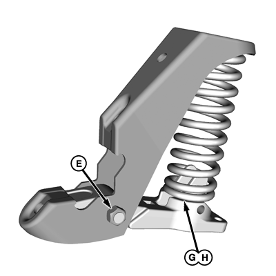
N110979-UN-05MAY14A - Tool, 7/8 x 18-1/2 in
B - Bolt and Nut, 1/2 x 5 in
C - Spring
D - Nut, 7/8 in.
E - Pivot Bolt
F - Flanged Washer
G - Spring Flat Area (Shaded)
H - Casting Flat Area (Shaded)
Install pivot bolt and nut (E). -
IMPORTANT: Align flat area (G) on spring with flat area (H) of casting to prevent spring damage.
Turn nut (D) counterclockwise to loosen spring (C) until pressure is against pivot bolt.
-
Remove bolt and nut (B).
-
Remove 7/8 x 18-1/2 in tool (A), with nut (D) and flanged washer (F). Return tool to holder when done.
-
Tighten pivot bolt nut (E) to specification.
Item Measurement Specification 3/4 in Pivot Bolt Nut Torque 651 N·m (480 lb·ft)
|
KB78086,0000EFD-19-20160429 |