Set Tread Width—Manual Adjust
IMPORTANT: Manual setting of tread width requires use of special tools and/or handling equipment. (See your John Deere dealer if your operation does not have the proper equipment to perform this procedure safely, as described here.)
Required tools are:
- Overhead hoist or lift bracket and jackstand
- JDG11094 sprayer support stand or equivalent
- Forklift or tractor with loader attachment
- Pull chain
NOTE: If sticking occurs, remove debris from axle knees and spray with TY25733 teflon based lubricant.
 CAUTION: To avoid injury or machine damage, make this procedure
in one wheel at a time, that the other wheels can stay on the ground
and blocked.
CAUTION: To avoid injury or machine damage, make this procedure
in one wheel at a time, that the other wheels can stay on the ground
and blocked.
-
Check if the solution tank is empty.
-
Place wheel chocks in front and behind the tires that stay at the ground.
CAUTION: Sprayer with spray boom is heavy. To avoid injury
or death, only lift and support the sprayer when it is empty. Only
jack wheels using the JDG11094 sprayer support stand or equivalent.
Do not apply jack pressure at any other location on the axle. Be
sure that the machine is stable before going under the frame. -
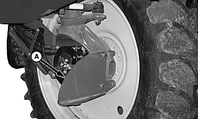
Raise one corner of the machine with the lift bracket (A) and a jackstand until wheel clears the ground by approximately 152 mm (6 in).
N83229-UN-20FEB09
N98533-UN-09MAY12A - Lift Bracket
B - JDG11094 Sprayer Support Stand
-
Place the JDG11094 sprayer support stand (B) under frame and lower machine onto support with bottom of tire 76—127 mm (3—5 in) off the ground.
-
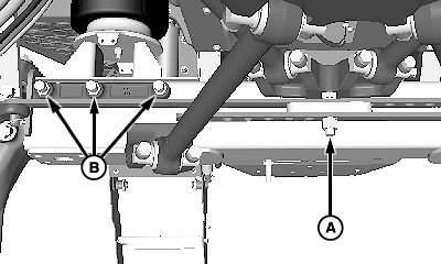
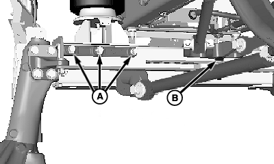
Loosen two or three turns, the screws and nuts (A): six on the left-hand side, and six on the right-hand side of the front and rear axles. There is one at middle of each axle too.
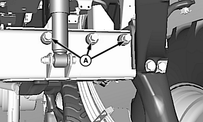
N84200-UN-14APR09Front Axle
N98342-UN-04MAY12Front Axle
N84201-UN-14APR09Rear Axle
N98343-UN-04MAY12Rear Axle
A - Screws and Nuts
B - Screws and Nuts
-
Remove only the screws and nuts (B).
-
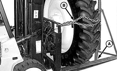
Position the forklift forks:
N83236-UN-20FEB09Extending Axle
A - Forklift Forks
B - Chain
-
Extending the axles: Position the forklift forks (A) against the bottom of the tire, and make sure that the fork ends do not contact the sprayer support stand. Place a chain (B) around the top of the tire and attach to forklift mast.
-
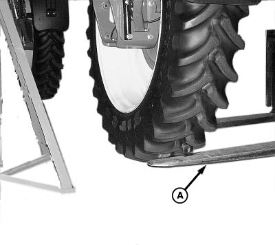
Retracting the axles: Position the forklift forks (A) against the bottom of the tire. Make sure that the fork ends do not pass through the internal side of the tire.
N76727-UN-14JUN07Retracting Axle
A - Forklift Forks
IMPORTANT: Be careful not to raise machine off the sprayer support stand. Forklift forks only need to be in contact with the bottom of the tire, not lifting it.
-
-
Lift the wheel slightly, only until the axle is free to move inside or outside the frame tube.
CAUTION: Take care when extending axle out to the widest setting.
There is no stop in the frames to prevent that the axle gets out of
the frame tube. Never put more than 406 mm (16 in) out of the axle. -
Move the forklift until the desired position is reached. A hole in the manual tread adjust strap has to align with the hole in the bracket where the lock nut and the screw were removed. So, maybe the wheel has to be slightly raised and lowered until the alignment is correct.
-
Remove the forklift.
-
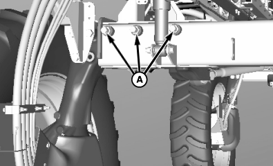
Tighten screws and nuts (A).
N98342-UN-04MAY12Front Axle Shown
N98343-UN-04MAY12Rear Axle Shown
A - Screws and Nuts
B - Screws and Nuts
-
Install screws and nuts (B). Apply anti-seize compound.
-
Adjust shim gap with the wheel off ground. See Adjust Shim Gap with Wheel Off Ground (Preferred), from step 6, in this Section.
-
Repeat entire procedure for the other wheels.
|
OU90500,000047D-19-20170425 |