Attaching Corn Head to Feeder HouseIMPORTANT: See your combine operator's manual for specific tires required when operating the header. Latch pins are not to be actuated with header on the ground. If multi-coupler must be actuated with header on ground, unhook cable from handle. 1. |
|
KM00321,0000033 -19-29AUG08-1/8 |
|
Sound horn, start engine and lower feeder house.
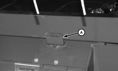
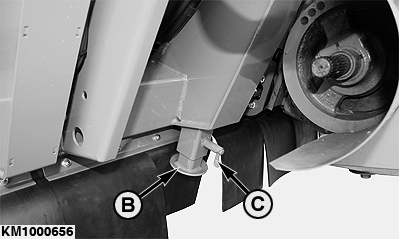
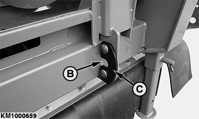
2. Drive combine slowly forward until feeder house is centered in attachment frame opening. 3. Raise platform completely, making sure two hooks (A) on feeder house catch front side of main frame beam of platform. 4. Set parking brake, shut off engine, remove key and lower safety stop. 5. Lock jackstands (B) on the r.h. and l.h. side in the highest position. To do this, pull out spring-loaded pin (C) and let it re-engage when the jackstand is in its final position. |
|
KM00321,0000033 -19-29AUG08-2/8 |
|
6.
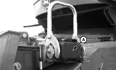
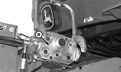
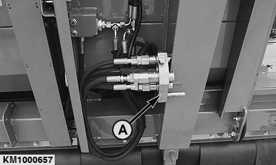
Remove cover (A) and clean multi-coupler face (B).
|
|
KM00321,0000033 -19-29AUG08-3/8 |
|
7.
Remove multi-coupler (A) from storage position.
|
|
KM00321,0000033 -19-29AUG08-4/8 |
|
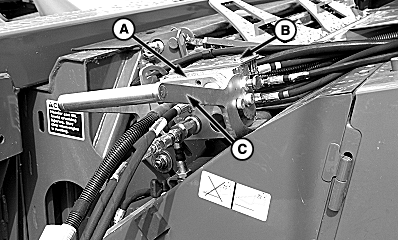
NOTE: To prevent damage to latching cable, a shear screw is attached to the handle. Attempts to actuate latching pins with header on ground will shear the screw on the handle. (See Extra Shear Screw Location later in this section.) With header attached, latch pins should move freely through latch plate holes. If latch pins do not extend through the latch plates, make sure that the latching plates on the header are properly adjusted. 8. Install multi-coupler (A) onto receptacle (B) and close handle (C). |
|
KM00321,0000033 -19-29AUG08-5/8 |
|
Button Lock Multi-Couplers
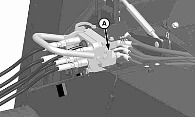
IMPORTANT: Failure to close multi-coupler fully so button lock can engage could result in the header falling off while harvesting or transporting. 1. When multi-coupler handle is fully closed, button lock (A) will automatically lock couplers together.
|
|
KM00321,0000033 -19-29AUG08-6/8 |
|
2.
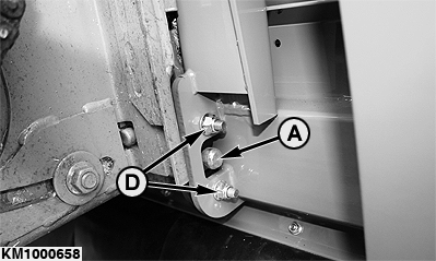
Latch pins (A) should move freely through latch plate holes (B) in header when multi-coupler is latched. This may require latch plate (C) to be adjusted.
3. If adjustment is needed: Loosen nuts (D) and align latch plate (C). 4. Tighten nuts (D) to M12 specification. Specification
|
|
KM00321,0000033 -19-29AUG08-7/8 |
|
5.
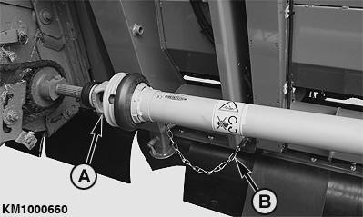
Remove drive shafts (A) on r.h. and l.h. side from storage position and install onto feeder house backshaft, making sure quick-attach collar locks fully.
6. Secure shield of drive shaft (A) with safety chain (B) against rotating. IMPORTANT: Drive shafts on r.h. and l.h. side are different. Make sure that drive shafts are always installed on the corresponding side.
|
|
KM00321,0000033 -19-29AUG08-8/8 |
