Adjusting Row Spacing
|
|||||||||||||||||||||||||
KM00321,000003D -19-01SEP08-1/5 |
|
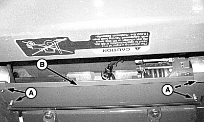
1. Remove and retain attaching hardware (A) and row unit drive shield (B). 2. Remove gatherer shields and points. (See Raising and Removing Center Gatherer Shields and Points in the Operating Header section for procedure.)
|
|
 CAUTION:
When working under the corn head, always place the cylinder safety stop in safety position to prevent header from lowering.
CAUTION:
When working under the corn head, always place the cylinder safety stop in safety position to prevent header from lowering.
KM00321,000003D -19-01SEP08-2/5 |
|
3.
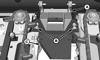
Remove cap screws (B), shield (C) and support (A).
|
|
KM00321,000003D -19-01SEP08-3/5 |
|
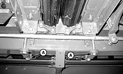
NOTE: To slide row units to desired location, with correct lifting devise lift and support under row unit skid plates keeping weight of unit on main frame. 4. Loosen bolts (A) of center two row units. Move both row units an equal distance to correct row spacing. Then move to the next outer row unit. Loosen bolts and move unit to the desired row spacing and continue until all row units are spaced correctly. Torque unit attaching bolts to specification. Specification
|
|
KM00321,000003D -19-01SEP08-4/5 |
|
5.
Position row unit shield and gatherer shield support for desired row spacing and reinstall cap screws (B) in shield (C) and gatherer shield support (A).
Specification
6. Reinstall shields and points on row units. 7. Connect sensor wire harness (if equipped) and push connector into hole of deck cover. Retain harness at yellow tape marks on harness to ensure proper slack for raising points. 8. Reinstall row unit drive shield. |
|
KM00321,000003D -19-01SEP08-5/5 |