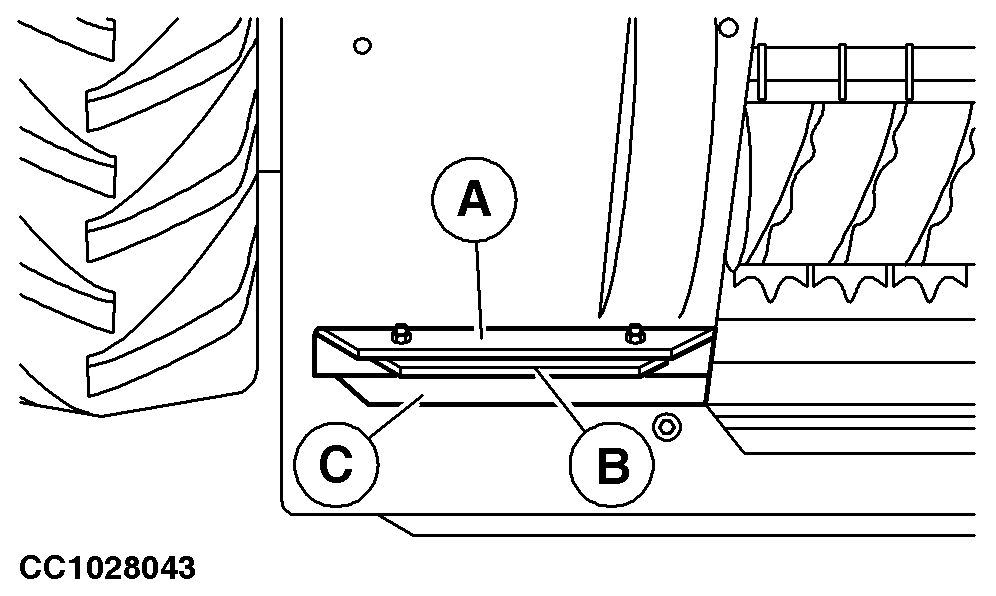
Attaching the 640C and 645C Pickups1. On each side of attaching frame, remove angle (A) and spacer (C) (if equipped).
|
|
KM00321,00000DA -19-08JAN09-1/6 |
|
2.
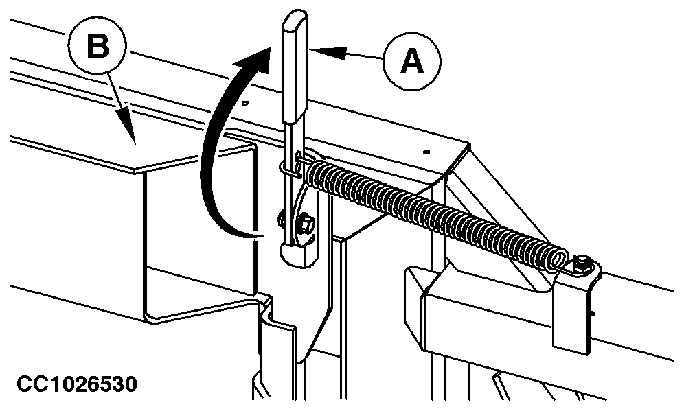
Lock oscillating frame (B) by means of lever (A).
|
|
KM00321,00000DA -19-08JAN09-2/6 |
|
3.
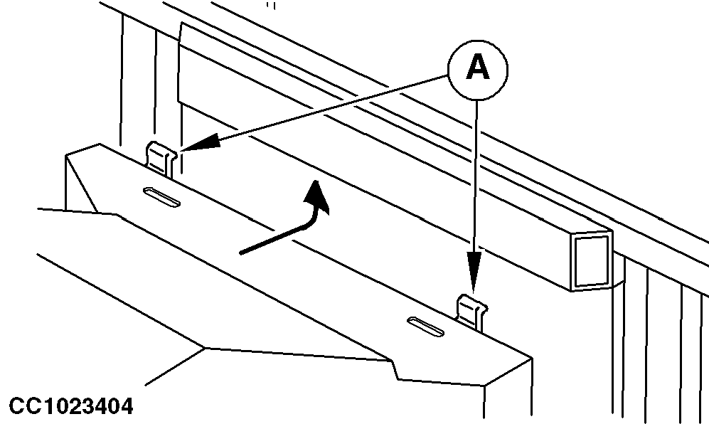
Lower the cutterhead assembly and position it parallel to the pickup. Move the harvester toward the pickup and raise the cutterhead assembly so that lugs (A) are located exactly underneath the pickup oscillating frame.
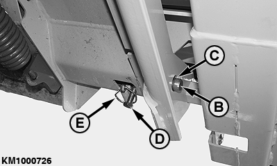
Continue to raise pickup until it is off ground. Remove quick-lock pin (E) (if equipped). Engage locking pins (B) in pickup attaching holes (C) by lifting and sliding bolts (D). Reinstall quick-lock pin (E) (if equipped). NOTE: If pickup attaching holes are not facing locking pin, adjust pickup attaching hole supports. (See Adjusting Pickup Attaching Hole Supports (640C and 645C) in this Section.)
|
|
KM00321,00000DA -19-08JAN09-3/6 |
|
4.
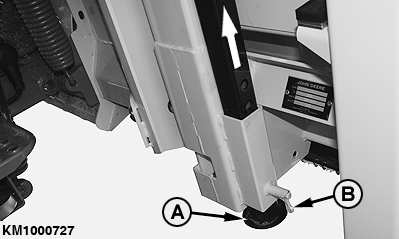
Lock jackstands (A) on the r.h. and l.h. side in the highest position. To do this, pull out spring-loaded pin (B) and let it re-engage when the jackstand is in its final position.
|
|
 CAUTION:
Make sure all jackstands are secured.
CAUTION:
Make sure all jackstands are secured.
KM00321,00000DA -19-08JAN09-4/6 |
|
5.
Connecting Drive Shaft
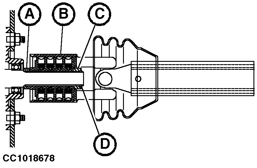
a. 640C and 645C Pickup Remove snap ring (D). Slide shims (A) on pickup input shaft. Slide cam clutch assembly (B) on pickup input shaft. Slide chamfered bushing (C) on pickup input shaft with chamfered side oriented to the outside. Install snap ring (D). b. 6000 and 7000 Series Harvester |
|
KM00321,00000DA -19-08JAN09-5/6 |
|
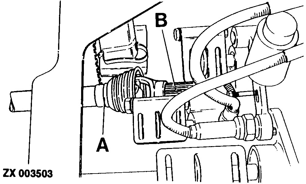
While pressing pin, slide universal jointed shaft (A) over splines of drive shaft (B) at length-of-cut transmission until pin engages. IMPORTANT: It is absolutely necessary to readjust harvesting unit float system after pickup has been attached. (See your self-propelled forage harvester Operator's Manual.)
|
|
KM00321,00000DA -19-08JAN09-6/6 |