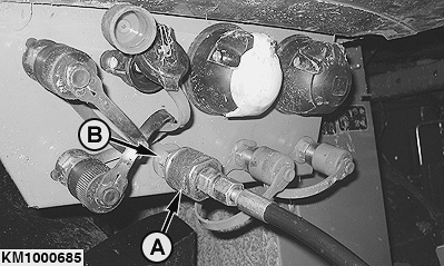
Detaching the 640C and 645C Pickups1. Disconnect Hydraulic HosePrior to detaching the pickup from the cutterhead housing, fully lower the crop deflector or the roller compression unit (option) to relieve pressure in hydraulic hose (A). Disconnect hose (A) from single-acting hydraulic outlet (B).
|
|
KM00321,00000DE -19-13JAN09-1/5 |
|
2.
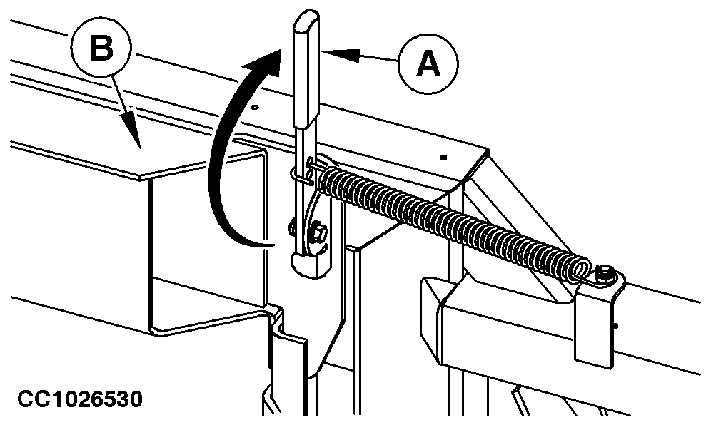
Secure oscillating frame (B) on pickup frame by means of lever (A).
|
|
KM00321,00000DE -19-13JAN09-2/5 |
|
3.
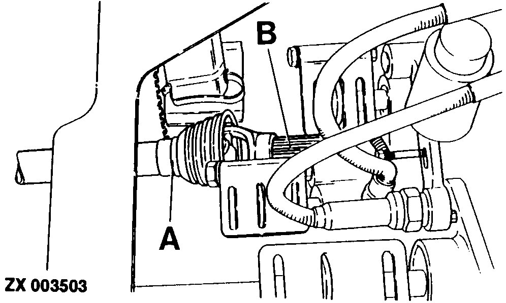
While pressing pin, slide universal jointed shaft (A) away from drive shaft (B).
|
|
KM00321,00000DE -19-13JAN09-3/5 |
|
4.
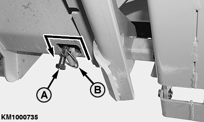
Remove quick-lock pin (B) (if equipped). As the pickup is not in contact with the ground, move bolts (A) in the pickup's attaching holes and put them securely in the detent position as illustrated. Reinstall quick-lock pin (B) (if equipped).
5. Lower the pickup until the gauge wheels rest on the ground. |
|
KM00321,00000DE -19-13JAN09-4/5 |
|
6.
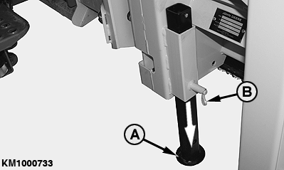
Lower the pickup jackstands (A) at either side and lock them at a suitable height. To do this, pull out spring-loaded pin (B) and let it re-engage when the jackstand is at the correct height.
7. Lower the cutterhead assembly further until it is clear of the pickup oscillating frame and it is possible to reverse the harvester. 8. Carefully reverse the harvester.
|
|
KM00321,00000DE -19-13JAN09-5/5 |